This is the 169th content shared by the platform.
 GPIO (General Purpose Input/Output) is a versatile interface used to connect microcontrollers, embedded systems, or other electronic devices to interact with the external world.GPIO is a highly flexible interface that can perform various functions such as digital input, digital output, analog input, and analog output. In embedded systems, GPIO typically serves as a bridge between chip pins and external circuits.Through GPIO, we can connect and interact internal signals or data with external devices or sensors. For example, GPIO can be used to read the state of buttons, control the on/off state of LEDs, or connect various sensors to read physical quantities such as temperature, humidity, and light intensity. Because GPIO is so versatile, almost all microcontrollers have GPIO functionality. Mastering GPIO is essential for developers working on embedded systems.
GPIO in STM32F407
 STM32F407 is a high-performance 32-bit MCU based on the ARM core, featuring 140 GPIO ports. Each port’s PAD module circuit is fundamentally consistent, capable of achieving four input modes: floating input, pull-up input, pull-down input, and analog input, as well as two output modes: push-pull output and open-drain output.
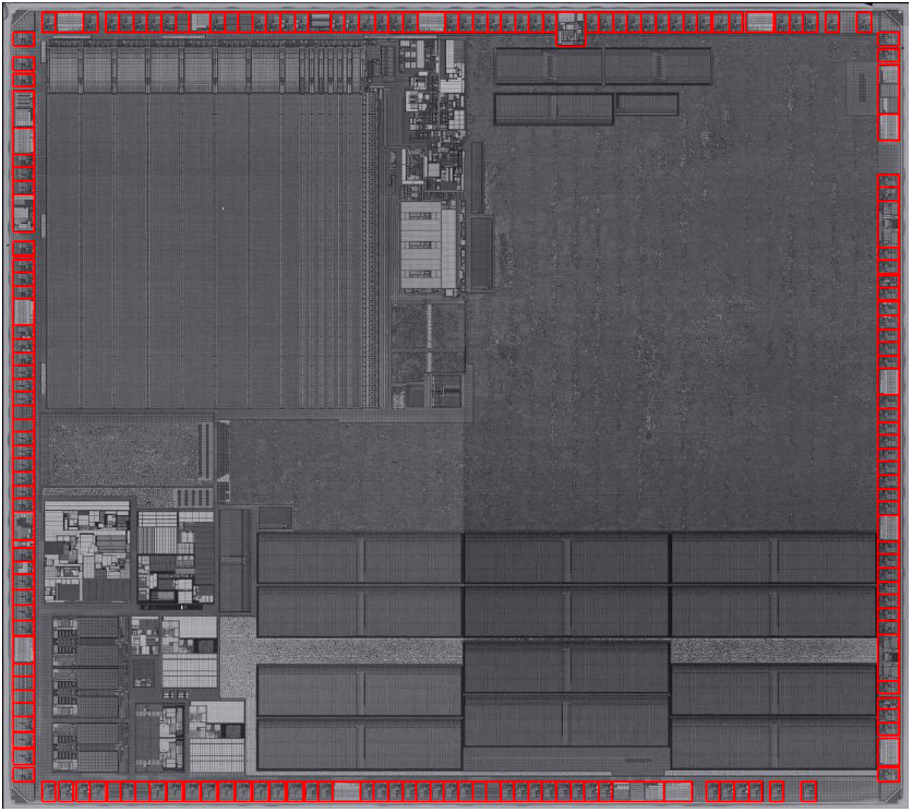 Overview of STM32F407 (POLY)Generally, GPIO consists of two parts: one part is the register, which stores the input or output data. By accessing the register, we can operate on the IO ports; simply put, a register is a memory unit with special functions. The other part is the PAD module, which is the driving circuit for the IO port, structured as shown in the following diagram.
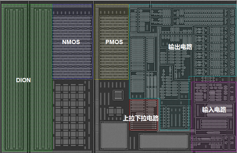 PAD Function Module in STM32F407 (POLY)
 Circuit Diagram of PAD in STM32F407
Simulation Analysis of GPIO in STM32F407

Working Principle of GPIO
The working principle of GPIO involves operations on multiple registers. For input functionality, the voltage level of a pin can be determined by reading a specific register; for output functionality, a specific register can be written to control the output high or low voltage of the pin.Additionally, GPIO supports interrupt functionality, which can generate interrupt requests when external events are triggered, allowing for real-time responses or handling specific events. When we talk about operating a peripheral or completing a specific function, we are essentially operating registers. As shown in the diagram below, this is the GPIO port output speed register, which can control the output speed of the pin by writing to a specific bit of the register.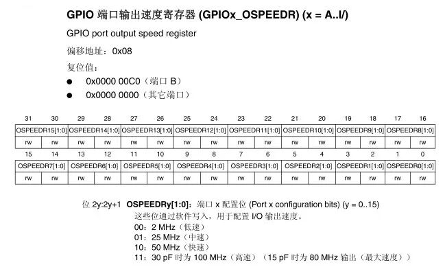 GPIO Registers
GPIO Operating Modes
Input Mode
Floating Input: The pin is in a floating state. In the floating input state, the IO level is uncertain and is entirely determined by external input, independent of the internal circuit, making it susceptible to interference. This mode is generally used for external button inputs or situations requiring flexible input impedance configuration.Pull-Up Input: A pull-up resistor is connected to the pin. The input level will not fluctuate due to external signals, ensuring stable input signals. When there is no external signal input, the pull-up resistor will clamp the input signal to a high level, causing the pin to always read a high signal. As shown in the diagram, the PAD signal is the IO port signal, and at this moment, there is no input to the IO port, with the pull-up resistor clamping the signal to a high level; PAD_Z is the output signal from the output circuit in the PAD module. This mode is suitable for input scenarios that require a default high level.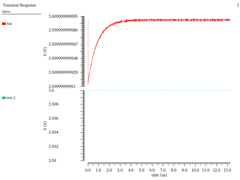 Pull-Up Input (No External Input)When an external high signal is input, the pull-up resistor has no effect; when an external low signal is input, due to the weak driving capability of the pull-up resistor, it cannot change the input logic state, and the input remains logic ‘0’, causing the pin to always read the input level signal, as shown in the diagram.
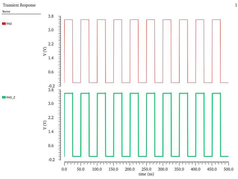 Pull-Up Input (With External Input)Pull-Down Input: A pull-down resistor is connected to the pin. The input level will not fluctuate due to external signals, ensuring stable input signals. When there is no external signal input, the pull-down resistor will clamp the input signal to a low level, causing the pin to always read a low signal. As shown in the diagram, the PAD signal is the IO port signal, and at this moment, there is no input to the IO port, with the pull-down resistor clamping the signal to a low level; PAD_Z is the output signal from the output circuit in the PAD module. This mode is suitable for input scenarios that require a default low level.
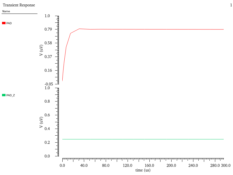 Pull-Down Input (No External Input)When an external low signal is input, the pull-down resistor has no effect; when an external high signal is input, due to the weak driving capability of the pull-down resistor, it cannot change the input logic state, and the input remains logic ‘1’, causing the pin to always read the input level signal, as shown in the diagram.
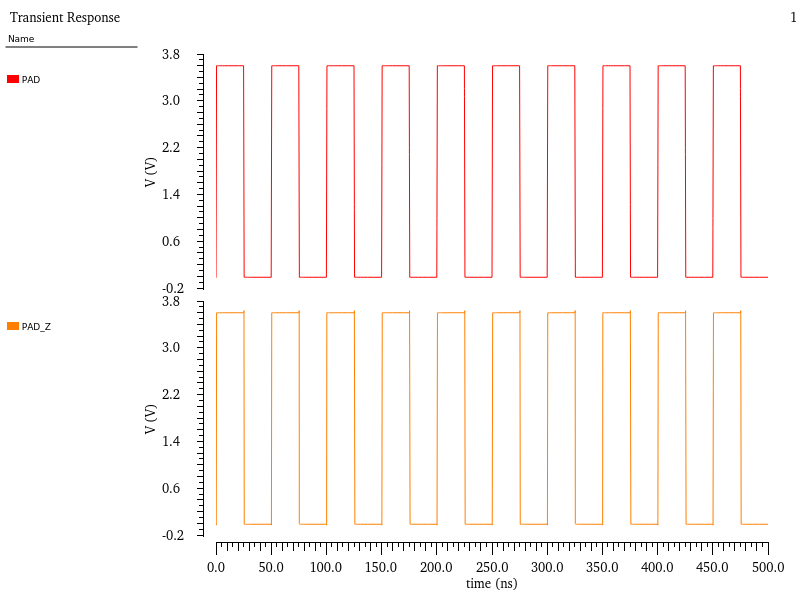 Pull-Down Input (With External Input)Analog Input: The voltage signal is directly sent to the analog module, and the signal enters without going through pull-up or pull-down resistors, bypassing the Schmitt trigger, and is sent to the analog module via another line. Therefore, it can be understood that the signal for analog input is unprocessed. As shown in the diagram, the PAD_ANA_VO is the IO port signal that has not gone through the Schmitt trigger. This mode is suitable for scenarios that require collecting analog signals.
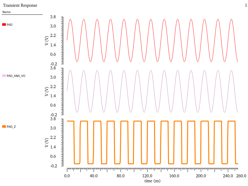 Analog InputWhen GPIO pins are used for ADC voltage input channels, the “Analog Input” function must be selected, as the signal only has two states (0 and 1) after passing through the Schmitt trigger, as shown in the PAD_Z signal in the diagram. Therefore, to collect the original analog signal, the signal source input must be before the Schmitt trigger.
Output Mode
Push-Pull Output: Push-pull output utilizes two different MOSFETs to achieve output. In push-pull output mode (PMOS + NMOS), by setting bits in the set/clear register or the output data register, the signal passes through the PMOS and NMOS, ultimately outputting to the IO port. It has the capability to output high and low levels.Push-Pull Output High Level: The value of the output data register activates the PMOS, outputting a high level;Push-Pull Output Low Level: The value of the output data register activates the NMOS, outputting a low level, as shown in the diagram, where PAD_D is the data input of the output circuit in the PAD module.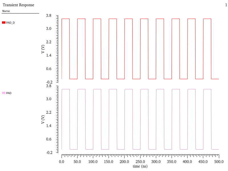 Push-Pull OutputOpen-Drain Output: The drain of the MOSFET is in an open state, hence this mode is called open-drain mode. Open-drain output cannot truly output a high level; during high level, it lacks driving capability and requires an external pull-up resistor to drive it. The pull-up voltage can be adjusted to meet the required voltage, thereby enhancing the driving capability of the external circuit.Open-Drain Output Low Level: The value of the output data register activates the NMOS, outputting a low level;Open-Drain Output High Level: The PMOS is not activated, requiring an external pull-up resistor to output a high level.Although open-drain output cannot output a high level internally, it has the following two advantages:
- Since we design our own pull-up, the voltage of this pull-up is determined by us, allowing us to adapt the pull-up voltage to the required high level for the external circuit, thus better accommodating various situations.
- The essence of open-drain output is actually an OD gate (OD: Open Drain). In digital circuits, an OD gate can achieve the function of a wired AND.
In output circuits, it is common to see situations where many parallel transistors are controlled by decoding or other methods, as shown in the diagram below, allowing for adjustment of output timing.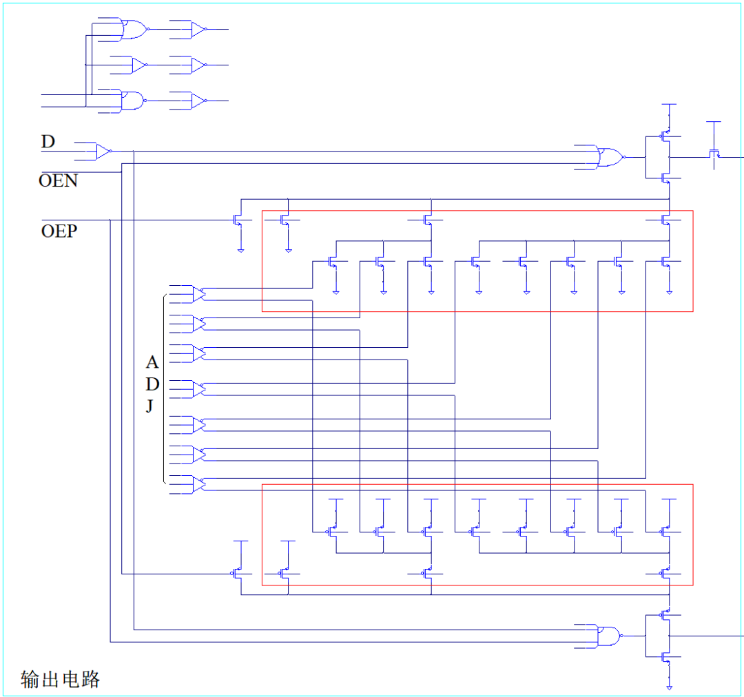 Output CircuitIn the circuit shown above, the more transistors in the red box that are turned on, the faster the output response. As shown in the diagram, the PAD_FAST signal indicates that all transistors are on, resulting in the fastest speed; the PAD_SLOW signal indicates that all transistors are off, resulting in the slowest speed.
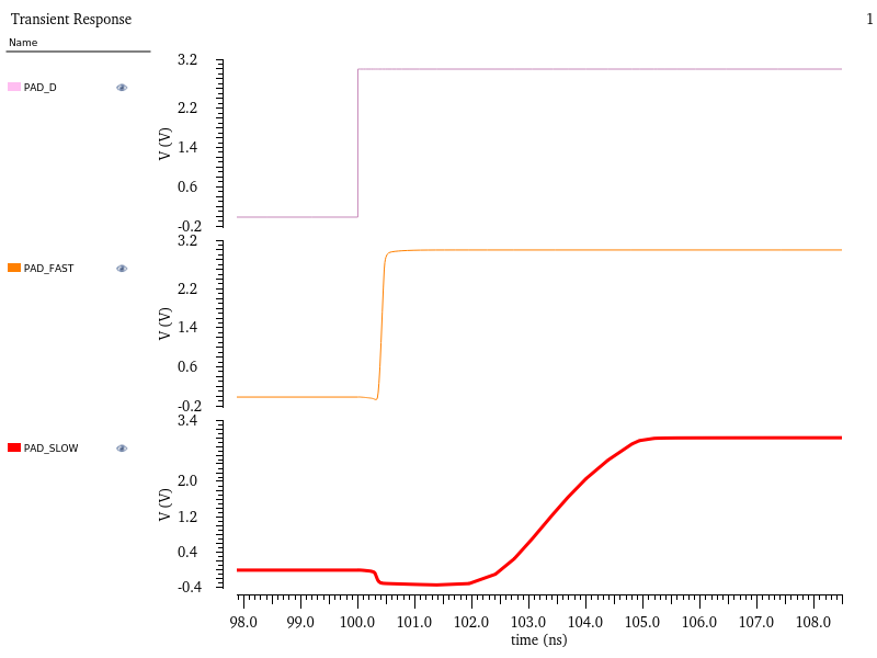 Output Speed Comparison
Conclusion
The above is a simulation analysis of GPIO in STM32F407. Overall, GPIO, as a general-purpose input/output interface, holds an important position in embedded systems and microcontrollers. Understanding and mastering the usage and precautions of GPIO is crucial for embedded system developers. We hope this article on GPIO helps everyone better understand and master GPIO knowledge.
About IPBrain Platform
The IPBrain integrated circuit big data platform belongs to Beijing Chip Vision Company. The IPBrain platform provides advanced chip technology information, patent information, market dynamics, and more for semiconductor industry clients. The most advanced process that the platform can analyze has reached 3 nanometers, with a maximum project scale exceeding 10 billion transistors and a maximum number of metal layers reaching 20.Currently, the platform has accumulated over 13,000 reports..
We welcome you to follow the IPBrain platform’s official account and website: https://www.ipbrain.com.cn, to stay updated on technology trends and market information, ensuring precise research and development without detours, and achieving product success faster.

Previous Exciting Recommendations
In-Depth Analysis | Simulation Analysis of SAR ADC Conversion Process in High-Performance Microcontroller STM32F407 with ARM Cortex-M4 Core
2025-01-02

In-Depth Analysis | Understanding the Working Principle of Chip Clock Lock PLL Phase-Locked Loop
2024-10-15

Shocking! This small module can manipulate the chip’s heartbeat, revealing the ultimate secret of the OSC oscillator!!
2024-12-04