As an important standard in the field of industrial communication, the technical specifications of RS-485 bus technology directly determine the stability, anti-interference capability, and transmission efficiency of the system. The following is a comprehensive analysis of the technical requirements of RS-485 from the aspects of electrical characteristics, mechanical structure, protocol specifications, and practical applications.
1. Electrical Characteristics Requirements
1. Differential Signal Transmission
RS-485 uses a balanced differential transmission method, requiring the differential voltage between the driver output terminals A/B to be ≥1.5V (typical value ±5V under no load), and the receiver must be able to recognize a differential signal of ≥200mV. This design effectively suppresses common-mode interference and allows for a maximum common-mode voltage range of ±7V.
2. Termination Impedance Matching
A 120Ω termination resistor must be configured at both ends of the bus (matching the cable characteristic impedance) to eliminate signal reflections. When the transmission rate exceeds 1Mbps or the cable length exceeds 100 meters, impedance matching must be strictly calculated, and segment termination techniques should be used if necessary.
3. Driver Capability Specifications
The standard specifies that a single driver must support at least 32 unit loads (UL), while modern chips like MAX485 can support up to 128UL. The driver output short-circuit current must be limited to 250mA to prevent damage to devices during bus conflicts.
2. Mechanical and Connection Requirements
1. Cable Selection Standards
It is recommended to use twisted pair shielded cables (e.g., AWG24), with a twist pitch less than four times the cable diameter. The shield should be grounded at a single point to avoid ground loop interference. The transmission distance is inversely proportional to the rate:
● Up to 1200 meters at 100kbps.
● Recommended not to exceed 100 meters at 1Mbps.
● High-speed applications at 10Mbps should be controlled within 15 meters.
2. Connectors and Wiring
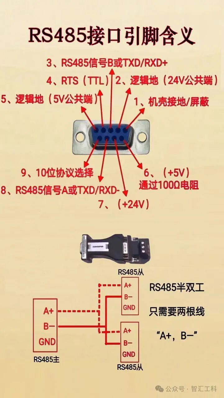
Use industrial-grade DB9 or terminal block connections, with contact materials that have anti-oxidation properties. The bus topology should avoid star structures, preferring daisy chain wiring, with branch lengths not exceeding 0.3 meters.
3. Protocol Layer Requirements
1. Bus Arbitration Mechanism
Multi-master conflict detection (CSMA/CD) must be implemented, with a typical response delay not exceeding 2 character times. Common protocols like MODBUS-RTU specify a frame interval of at least 3.5 character silence time.
2. Fault Protection Design
The receiver input impedance must be ≥12kΩ, and it should automatically enter a high-impedance state when not connected. The bus must have open/short circuit detection capabilities, and some chips like SN65HVD72 have built-in failure protection bias circuits.
4. Environmental Adaptability Requirements
1. EMC Performance
It must pass the 3V/m RF immunity test according to IEC61000-4-3 standards, and electrostatic discharge (ESD) protection must reach ±15kV (contact discharge). In industrial scenarios, it is recommended to use isolated 485 modules with isolation voltage ≥2500Vrms.
2. Operating Temperature Range
Industrial-grade chips require an operating temperature of -40℃ to +85℃, with humidity tolerance of 95%RH (non-condensing). For outdoor installations, UV protective tubing should be used.
5. Key Points for Application Practice
1. Grounding System Design
The communication ground (SG) and chassis ground (PG) should be separated, using single-point grounding or magnetic coupling isolation. For long-distance transmission, it is recommended to use opto-isolators.
2. Network Expansion Solutions
When exceeding 32 nodes, repeaters must be added, with each segment of the bus not exceeding 1200 meters. Fiber optic repeaters can achieve transmission extensions of over 5 kilometers.
3. Diagnostic and Maintenance Interface
Reserved test points for measuring the voltage between A/B lines (normal value 1.5-5V) are recommended, along with integrated LED status indicators (send/receive/fault).
Currently, RS-485 technology is developing towards high-speed and intelligent applications. For example, TI’s THVD series chips support 50Mbps transmission while being compatible with traditional standards. In actual deployment, it is also necessary to combine standards such as ISO/IEC 8482 and TIA/EIA-485-A for system validation to build a highly reliable industrial communication network.