Follow “Technical Training” focused on automation education for 14 years
A number system, also known as a counting system, is a method of representing numerical values using a fixed set of symbols and unified rules.
Any number system consists of two basic elements: base and positional value.
Base: The number of digits used in the number system.
For example, the base of the binary system is 2; the base of the decimal system is 10.
Positional Value: The size of the value represented by 1 at a certain position in the number system (the value of its position).
For example, in the decimal number 123, the positional value of 1 is 100, that of 2 is 10, and that of 3 is 1.
In binary 1011, the positional value of the first 1 from the left is 8, that of 0 is 4, the second 1 is 2, and the third 1 is 1.
The commonly used number systems in PLC include: Decimal, Binary, Hexadecimal, and Octal.
Additionally, BCD code and ASCII code are also occasionally used.
Decimal (Decimal notation):
For example, 1234=1*10^3+2*10^2+3*10^1+4*10^0, carrying over every ten, with a base of 10, individual digits are 0-9, and each digit’s coefficient is multiplied by the base (10) raised to the power of N, where N is its position.
Binary (Binary notation):
For example, 1101=1*2^3+1*2^2+0*2^1+1*2^0=13, carrying over every two, with a base of 2, individual digits are only 0 and 1, and each digit’s coefficient is multiplied by the base (2) raised to the power of N, where N is its position. From the 3rd position to 0, the values are 8, 4, 2, 1, so binary is also called 8421 code. If representing signed numbers, the highest bit indicates the sign, 0 for positive and 1 for negative. Positive numbers are represented in binary’s original form; negative numbers are stored in two’s complement, which involves inverting the original bits and adding 1.
Hexadecimal (Hexadecimal notation):
Carrying over every 16, generally represented using digits 0 to 9 and letters A to F (or a~f), where A~F represent 10~15, these are called hexadecimal digits.
Octal (Octal notation):
Carrying over every 8, individual digits are 0-7, commonly used for addressing in PLC, with less application in data operations. BCD (Binary-Coded Decimal): also known as binary-coded decimal or base-10 code, uses 4 bits of binary to represent each decimal digit from 0-9. Clocks typically use BCD for storage.
ASCII (American Standard Code for Information Interchange):
A computer coding system based on Latin letters, mainly used for displaying modern English and other Western European languages. It is currently the most widely used system and is equivalent to the international standard ISO/IEC 646. Data storage in PLC can only be in the form of 0 and 1; other data can be converted to binary through base conversion, but the representation of letters and some special symbols requires a set of agreed conversion rules, hence the ASCII code was established by relevant American standardization organizations.
Floating Point (float):
Also known as real numbers, floating point is a numerical representation of a specific subset of rational numbers, used in computers to approximate any real number. Specifically, this real number is obtained by multiplying an integer or a fixed-point number (the mantissa) by a power of a base (usually 2 in computers). This representation method is similar to scientific notation with a base of 10.
In binary scientific notation: S=M×2^N
It mainly consists of three parts: sign bit + exponent (N) + mantissa (M). For float data, its binary representation has 32 bits, where the sign bit is 1 bit, the exponent is 8 bits, and the mantissa is 23 bits.
Sign bit: 0 represents positive, 1 represents negative.
Exponent: Here the exponent uses biased representation, for float data, the specified bias is 127, the exponent can be positive or negative, for 8-bit binary, its range is −128 to 127. For example, if the actual value of the exponent for float data is 2, then adding 127 gives 129, and its exponent representation is 10000010.
Mantissa: The significant digit part, which is part of the binary bits (the binary bits after the decimal point); since it is specified that the integer part of M is always 1, this 1 is not stored.
Example Illustration
To convert the float data 125.5 to standard floating-point format, the binary representation of 125 is 1111101, and the fractional part represented in binary is 1 (the fractional part multiplied by 2, if less than 1, it is 0, if greater than 1, it is 1, continue multiplying the fractional part by 2 until it reaches 0), thus the binary representation of 125.5 is 1111101.1. Due to the specification that the integer part of the mantissa is always 1, it is represented as 1.1111011*2^6, the exponent is 6, adding 127 gives 133, thus represented as 10000101, and for the mantissa, the integer part 1 is removed, and 0s are added to the right to make its length reach 23 bits, resulting in 11110110000000000000000. Therefore, its binary representation is: 0 10000101 11110110000000000000000
So how are these number systems converted?
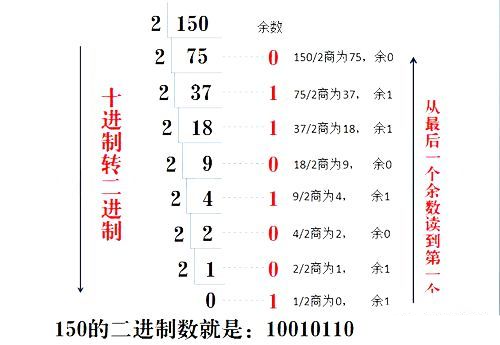
1. The method to convert decimal to binary is:
Decimal number divided by 2 remainder method, that is, divide the decimal number by 2, the remainder is the number at the positional value, the quotient continues to be divided by 2, and repeat this until the quotient is 0. (Specific usage is shown in the image below)
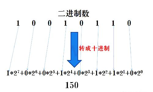
2. The method to convert binary to decimal is:
Expand the binary number by positional value and sum to get the decimal number. (Specific usage is shown in the image below)
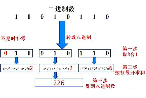
3. The method to convert binary to octal is:
3 binary digits are expanded and summed to get 1 octal digit. (Note, converting 3 binary digits to octal starts from right to left, padding with 0 if insufficient). (Specific usage is shown in the image below)
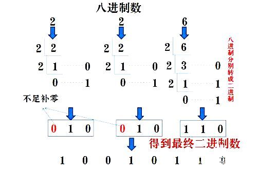
4. The method to convert octal to binary is:
Octal numbers are converted to binary using the remainder method, where each octal digit corresponds to 3 binary digits, padding with zeros on the left if insufficient. (Specific usage is shown in the image below)
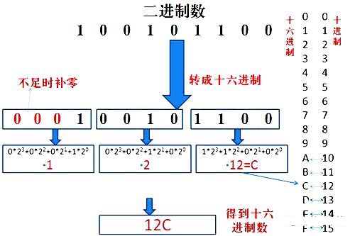
5. The method to convert binary to hexadecimal is:
Similar to the binary to octal method, octal is taken three at a time, while hexadecimal is taken four at a time. (Note, converting 4 binary digits to hexadecimal starts from right to left, padding with 0 if insufficient). (Specific usage is shown in the image below)
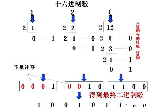
6. The method to convert hexadecimal to binary is:
Hexadecimal numbers are converted to binary using the remainder method, where each hexadecimal digit corresponds to 4 binary digits, padding with zeros on the left if insufficient. (Specific usage is shown in the image below)
7. There are two methods to convert decimal to octal or hexadecimal:
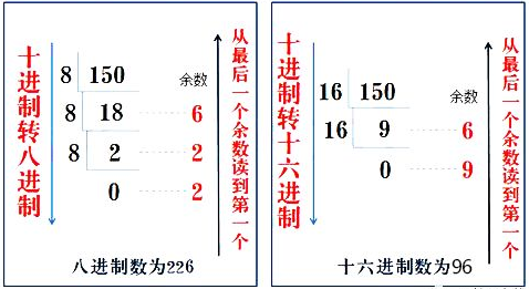
The first: Indirect method—convert decimal to binary, then from binary to octal or hexadecimal. No further image explanation is provided here.
The second: Direct method—convert decimal to octal or hexadecimal by dividing by 8 or 16 and taking the remainder until the quotient is 0. (Specific usage is shown in the image below)
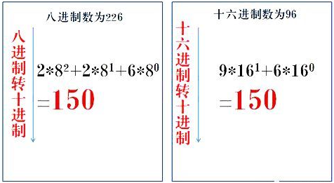
8. The method to convert octal or hexadecimal to decimal is:
Expand the octal and hexadecimal numbers by positional value and sum to get the decimal number. (Specific usage is shown in the image below)
9. BCD code to decimal:
Since BCD code uses four bits of binary to represent one decimal digit, the conversion method is similar to the binary to hexadecimal “four at a time” method, combining four bits and converting to decimal gives the decimal value. The above introduces the commonly used number systems in PLC and their conversion methods, aimed at helping beginners understand the meaning of number systems and conversion rules. In practical use, a programmer’s calculator provided by a computer can easily perform these calculations.
Source: Internet, copyright belongs to the original author, infringement will be deleted
Previous · Recommendations
2021 Electrical Beginner Exam Question Bank Complete Edition (with answers)
Latest Electrical CAD Drawing Software, with super detailed installation tutorial!
Latest Electrical Drawing Software EPLAN, with super detailed installation tutorial!
What does a perfect PLC program look like? (with beginner programming advice)
Comprehensive Electrical Calculation EXCEL sheet, automatically generated! No more need for help with electrical calculations!
Siemens and Mitsubishi instruction manual, only by gathering these do you realize PLC programming is so easy!
Bluetooth headsets, electrical/PLC beginner books are generously given away? Hurry to claim your electrical gift!
Basic skills in PLC programming: Ladder diagrams and control circuits (with 1164 practical cases of Mitsubishi PLC)
Still can’t understand electrical diagrams? Electrical diagram reading basics, simulation software available, quickly get hands-on with theory and practice!
Do you consider yourself a PLC programming expert? Have you reached these 6 standards? (with 12 programming tips from senior engineers)
 Like it? Click here
 Free PLC and Electrical Courses, click to read the original text