Due to time constraints, I will keep this article brief. This article is my original work, based on my own experiences, and not written by anyone else. When copying or quoting this article, please indicate the source; otherwise, I reserve the right to pursue legal action, so please take note.
This article is quite technical, and I will not provide further explanations for terms that are unclear.
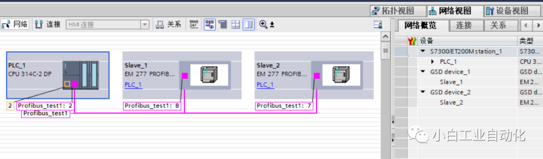
Profibus, as a communication method, has been widely used in the field of industrial control due to its unique advantages. This article discusses a Profibus communication case between Siemens S7-300 and Siemens S7-200 PLCs (one S7-300 and two S7-200).
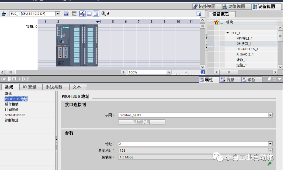
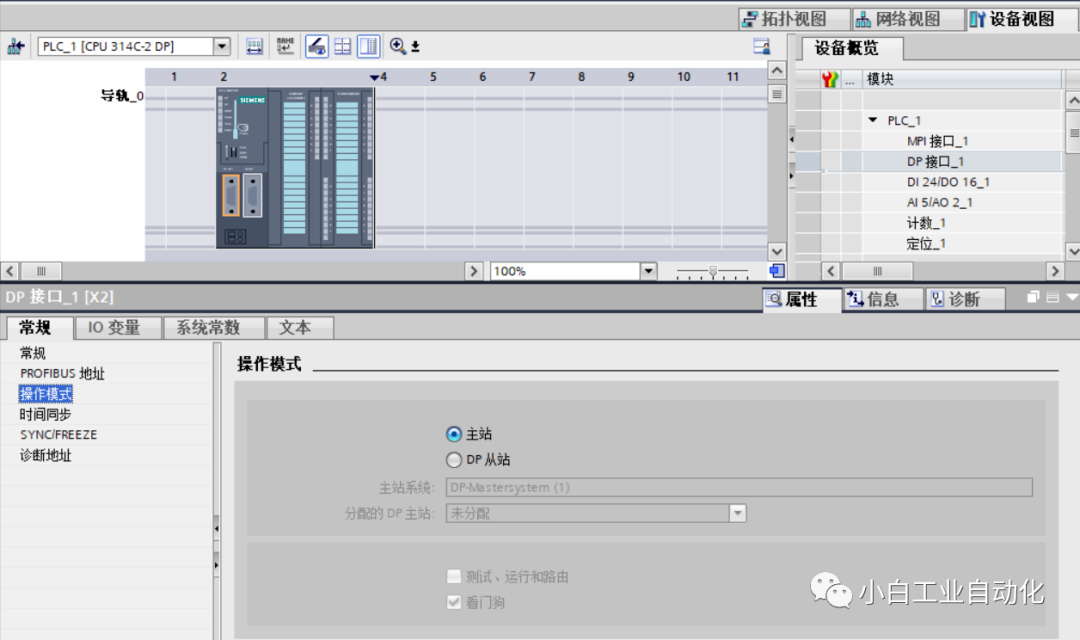
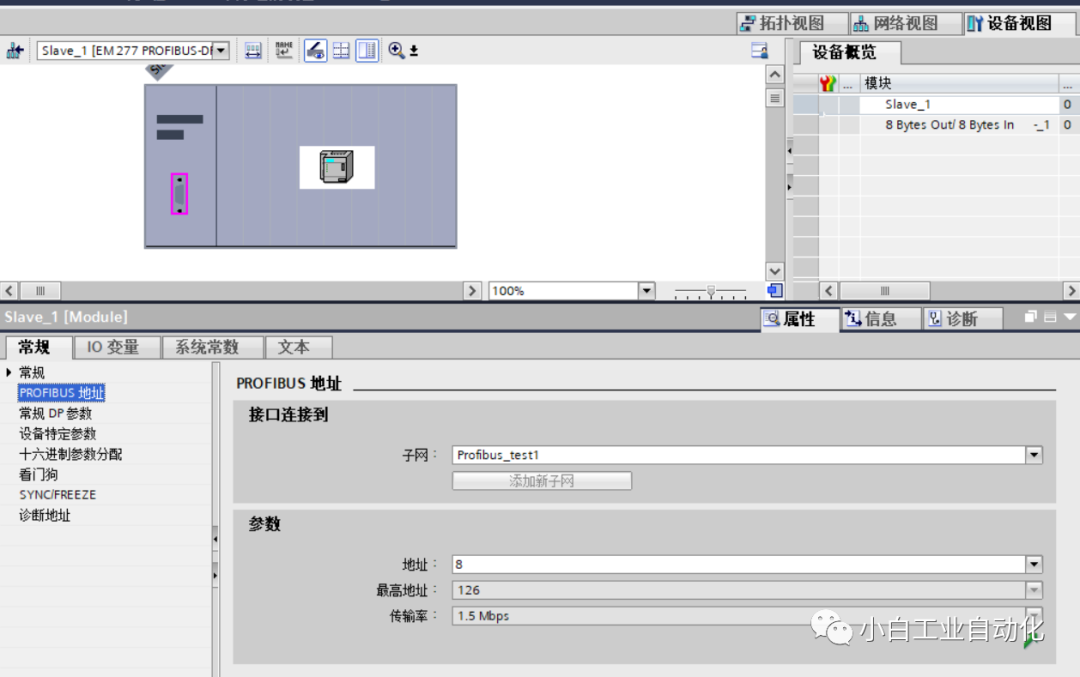
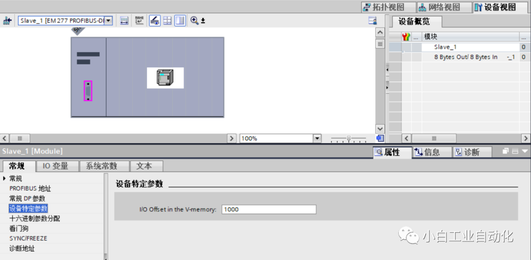
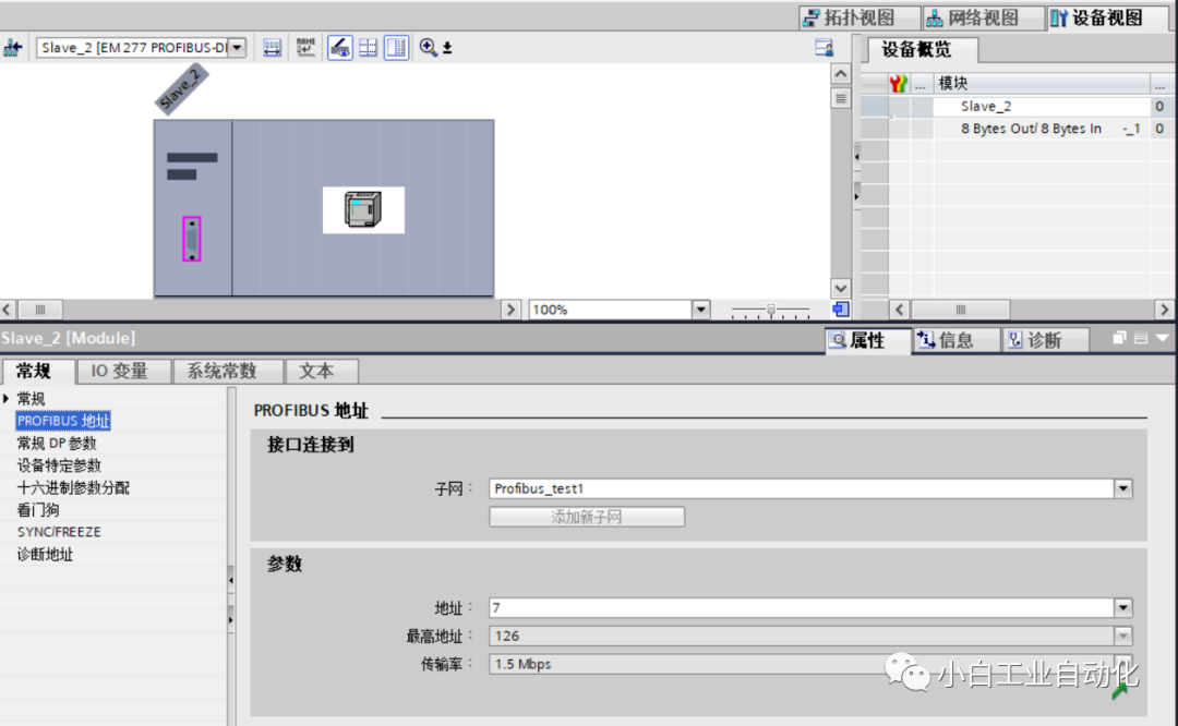
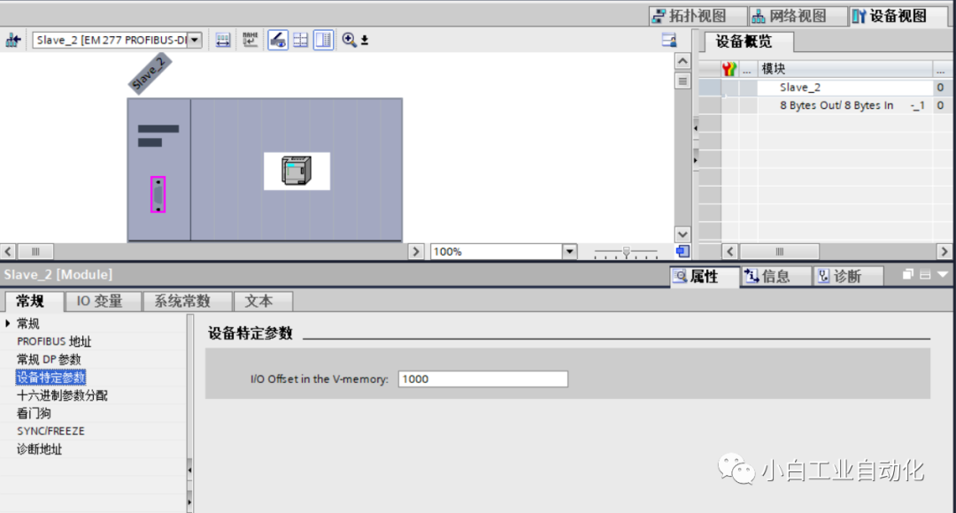
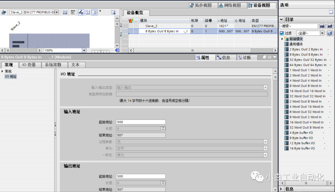
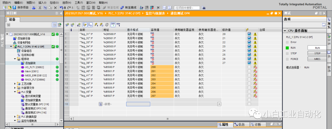
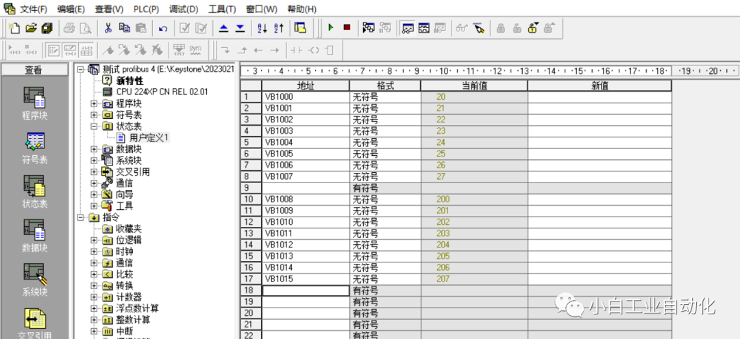
Please first download the PROFIBUS Technical Reference Comprehensive Document from the Siemens Automation official website. Here, I will briefly explain the process without going into too much detail. First, ensure the power is off (ignore this step at your own risk; if something goes wrong, don’t blame me, I have warned you). Connect using the DP plug, ensuring that the two EM277 modules are correctly connected to their respective 200 expansion slots. Adjust the X10 and X1 address knobs on the EM277 modules, and then open TIA Portal to add the GSD for EM277, followed by configuring the hardware for the S7-300; the S7-200 does not require configuration. Set up the monitoring table and configure the monitoring status to determine whether the communication is successful.
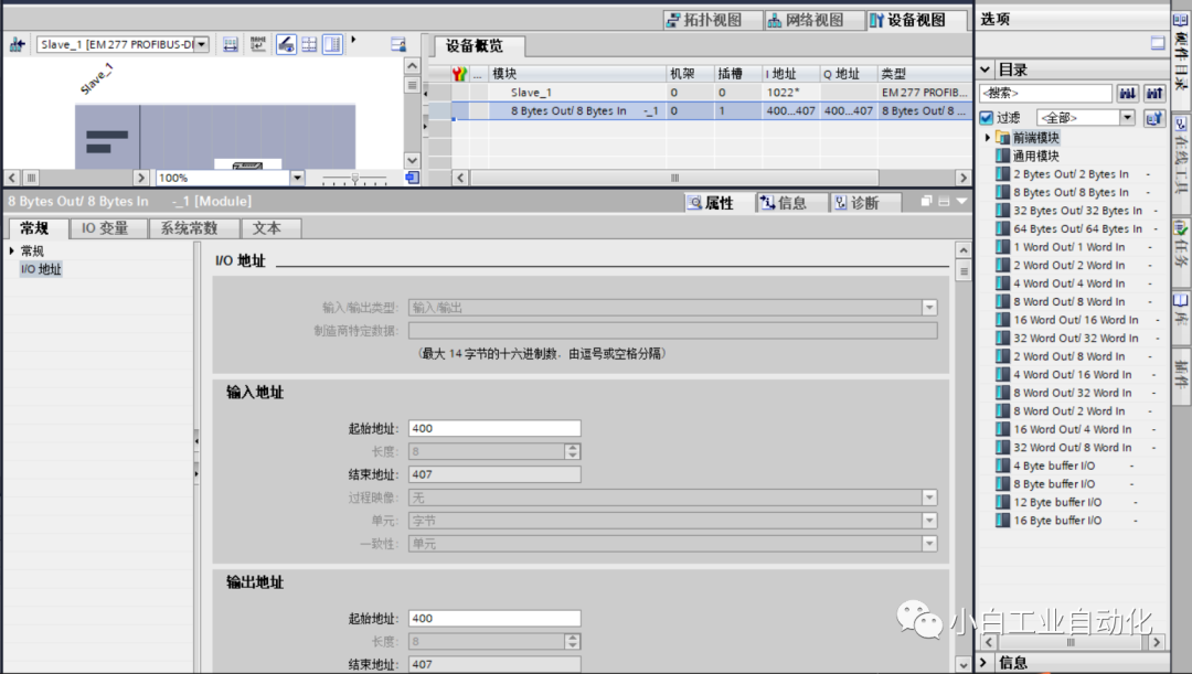
A special reminder: the communication I/O addresses for the S7-300 are within the allowable range of physical addresses Q:PX, QX:PX, I:PX, IX:PX, etc. When entering these, simply type QPX, QXPX, IPX, IXPX, and the PLC will automatically recognize them.
This physical address is not the I/O address on the PLC terminal; it is merely referred to as a “physical” address by Siemens, but it is essentially a virtual address with range limitations.
Next, I will provide some images for you to compare and understand.