Second-OrderRC Equivalent Circuit Model
The block diagram of the second-order RC equivalent circuit model is shown below.
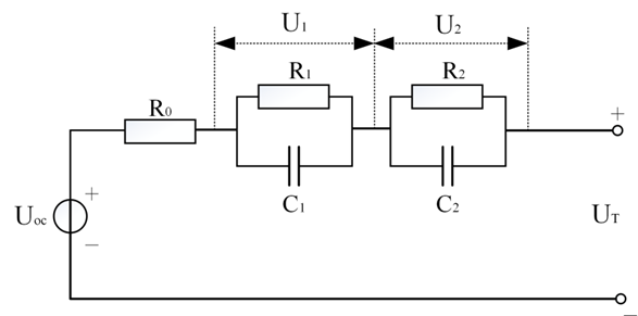
Where, Uoc represents the ideal voltage source, which has a nonlinear relationship with SOC; R0 represents the internal resistance, R1 R2 are the polarization resistances, C1 C2 are the polarization capacitances, Ut represents the terminal voltage of the battery. According to Kirchhoff’s law, the system equation and observation equation are as follows. Define the discharge current direction as positive and the charging current as negative.
System Equation:
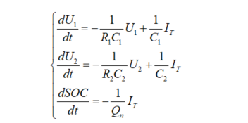
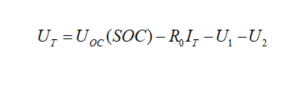
Observation Equation:
Definition of SOC Algorithm
The definition of SOC is State of Charge, abbreviated as SOC, which refers to the available state of the remaining charge in the battery, and can be described by the following ratio:
SOC = (Remaining Capacity / Rated Capacity) * 100%
Rated Capacity
People often refer to it as the nominal capacity, which is the battery’s xxAH, but where does this AH come from?
So the question arises, why is there this difference? This is related to the electrochemical reactions of the cell; under different temperatures and rates, the number of Li+ ions released by the cell varies, but this does not mean that the cell’s discharge capability is different. The ability of the cell to release Li+ is consistent at any temperature when discharged at the minimum rate, which is determined by the chemical characteristics of the cell.
The rated capacity is also related to SOH, because as the battery ages, the rated capacity changes. From the electrochemical mechanism, with the increase in charge and discharge cycles, the SEI film gradually thickens, consuming Li+, which leads to a decrease in the amount of charge the cell can release! Thus, the rated capacity decreases.
In summary, when calculating SOC, the strategy for determining Qmax should be based on actual conditions and needs.
As for the remaining capacity, it is obtained by Qmax – the actual capacity from ampere-hour integration, and through a ratio, the SOC value can be derived.
Error Mechanism:
Before this, let’s discuss the two mechanisms that cause errors in SOC: cumulative error and random error. Cumulative error is mostly due to inaccurate ampere-hour integration, leading to long-term uncorrected errors, which are specified in technical protocols and standards (currently mostly 5%), while random error is caused by device instability, initial value errors, etc. When these occur, SOC correction calculations are performed to quickly set the SOC to a stable state.
Charging Correction:
Whether it is slow charging or fast charging, when charging ends, that is, when the cell voltage reaches the cutoff voltage, SOC may not be SOC due to cumulative error, at this moment it needs to be corrected to 100%
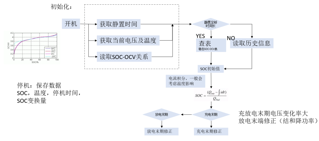
Static Correction:
When the battery is in a static state, the OCV value obtained from the table is quite accurate, but it cannot change instantly from one value to another when the vehicle starts, so a correction factor K is needed, to perform ampere-hour integration correction after a period of time following the start.
Dynamic Correction:
When the battery is in a dynamic discharge state, if the discharge current exceeds 10A and remains stable for a period of time, the current actual SOC can be calculated from the table, and by comparing the deviation with the actual SOC, the correction factor K can be calculated from the table for ampere-hour integration and reverse correction.
Correction Calculation Formula:
SOC(%) = (Ampere-hour integration consumed SOC * K) / SOC_max
- Normal situation K=1
- Overestimation correction K>1
- Underestimation correction K<1
Static correction logic: