In this article, we will introduce how to quickly set up Ethernet on an FPGA (using LWIP). For this purpose, we will use MicroBlaze as the main CPU to run its application.
LWIP is a good starting point for designing Ethernet with bare metal, on which we can easily adjust the software application to provide more detailed applications. The use of the LWIP Echo Server allows us to first determine whether the underlying hardware design is correct.
The core of this design is the AXI Ethernet Lite IP module in Vivado IP (I am using Vivado 2023.1 for this project). The AXI Ethernet Lite IP is suitable for 10 or 100 Mbps Ethernet links. This provides a resource-light Ethernet interface, making it an ideal choice for our low-cost devices (such as the Artix 7 FPGA). With a simple Ethernet interface, designers can use Ethernet for command and control of the final application.
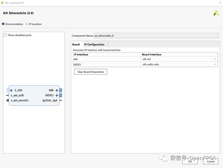
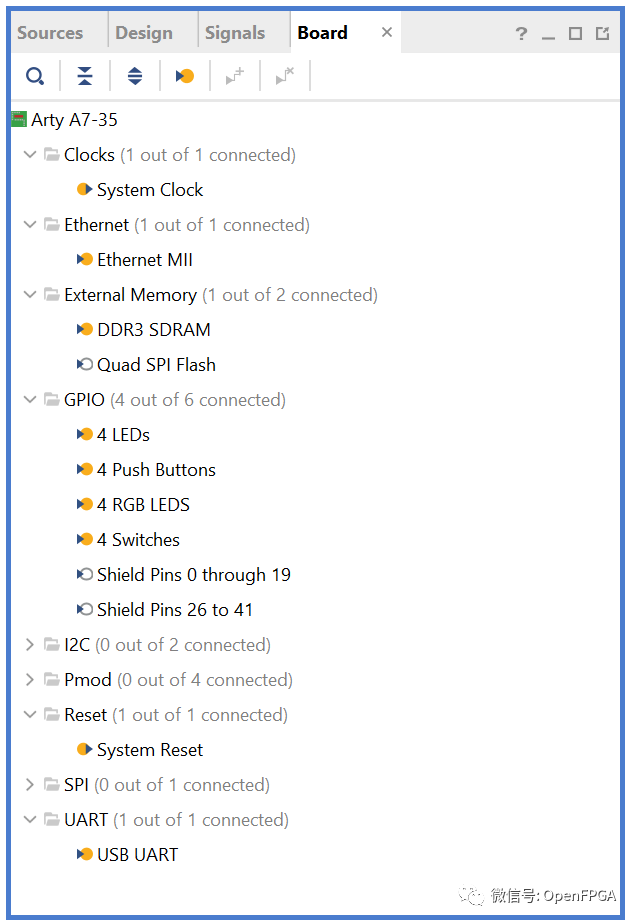
To verify this IP, we will use the Arty A7-35T board. After creating the project, create a block diagram and add the following IP from the Board tab of the IP Designer.
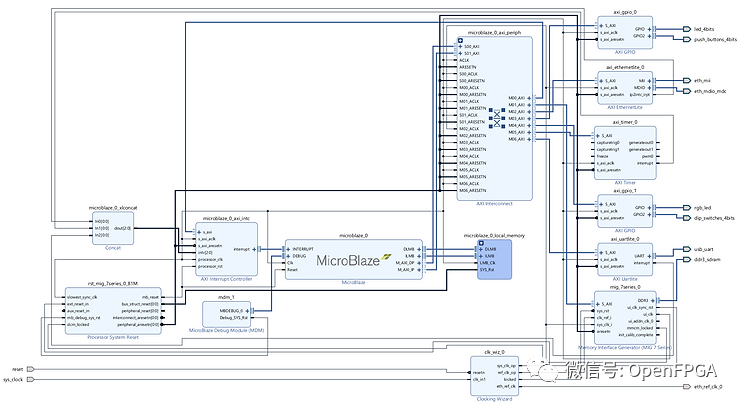
The complete design can be recreated using the TCL scripts stored in the Git Repo. Key design points include using the DDR clock output to provide clock signals for all AXI networks except for the AXI Ethernet Lite IP module (with a clock frequency of 100 MHz).
The system clock frequency of the DDR is 100 MHz, and the reference clock frequency is 200 MHz. The DDR interface operates at a frequency of 324.99 MHz, with an interface frequency that is 1/4 of most AXI interface frequencies (81.2475 MHz).
In addition to the AXI Ethernet Lite IP, we also need to provide a 25 MHz reference clock to configure the Ethernet PHY.
The design in Vivado is shown below.
With the available bitstream, export the XSA from Vivado and import the XSA into a new application project in Vitis.
Target the MicroBlaze processor and select the LWIP Echo Server application.
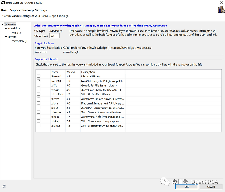
After creating the project, you can build the application and platform. Note that when compiling LWIP in Vitis 2023.1, there is an error in the xadaptor.c file, where line 388 has two state declarations, one for a 16-bit variable and one for a 32-bit variable. If this occurs, comment out the 16-bit declaration and recompile the design.
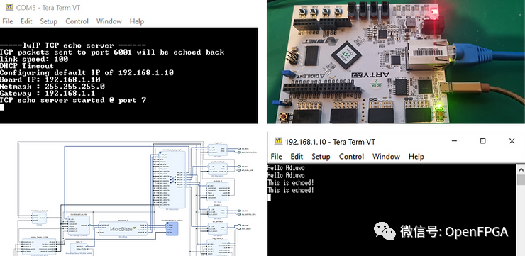
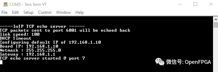
After connecting the Arty A7 board to the PC via an Ethernet cable, you can download and run the application on the Arty A7 board.
The terminal will output the IP address and provide all commands sent to port 7.
To be able to connect to the Arty A7 via Telnet, we first need to configure the host’s IP address to be similar to that of the Arty A7.
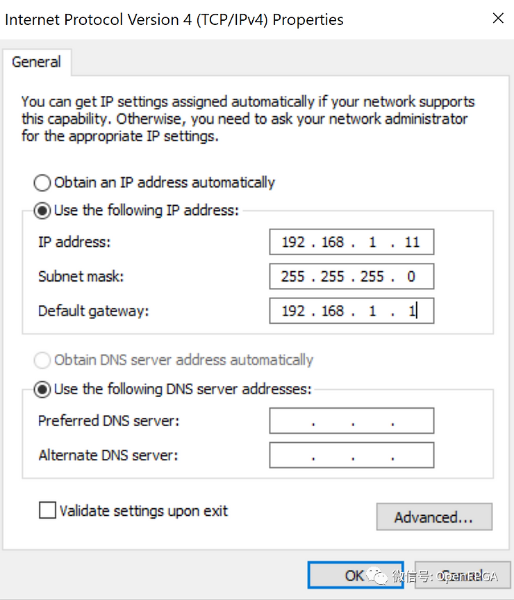
Once the IP settings on the host are correct, we can open a Telnet session with the Arty Board and send commands to echo back.
It is best to set the terminal program to perform local echo and append CR/LF to the messages.
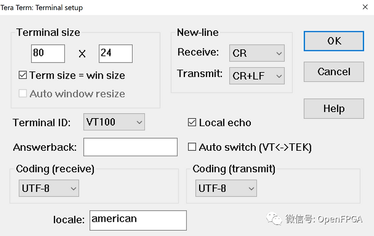
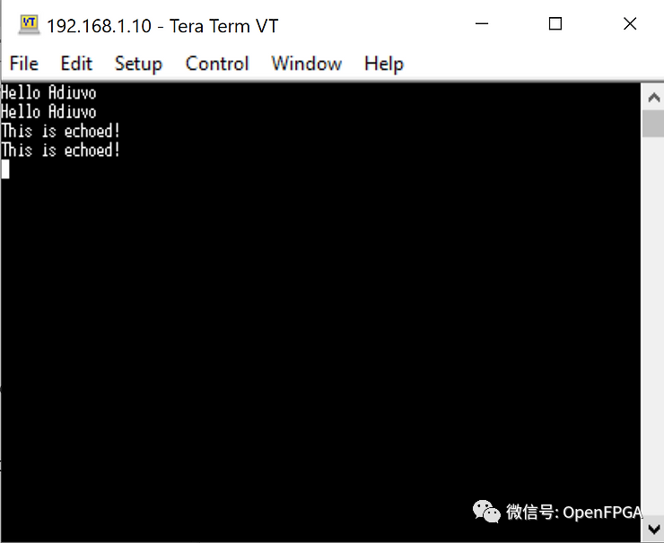
Then we can input text and watch it echo back.
That concludes today’s journey, providing us with a good starting point for developing Ethernet applications, and we can subsequently develop new Ethernet projects.