▲ Click the above Lei Feng Network to follow

Realize remote control of various electrical devices through the Internet or GPRS system.
This article is transferred from | Embedded ARM
This article introduces a smart home controller that uses ZigBee technology to integrate many relatively independent household appliances into a unified smart home system, thus facilitating local operations of various electrical devices in the home, while also enabling remote control of various electrical devices through the Internet or GPRS system.
ZigBee is an emerging wireless network technology characterized by short range, low complexity, low power consumption, low data rate, and low cost, with broad application prospects in many fields.
The smart home is a multifunctional integrated technology system that serves as a platform for residential homes, utilizing advanced computer technology, communication technology, network technology, control technology, and information technology to organically connect various electrical devices in the home through some form of network for comprehensive management and control, providing people with a comfortable, safe, convenient, environmentally friendly, and efficient living environment.
This article introduces a smart home controller that uses ZigBee technology to integrate many relatively independent household appliances into a unified smart home system, thus facilitating local operations of various electrical devices in the home, while also enabling remote control of various electrical devices through the Internet or GPRS system.
1. Introduction to ZigBee Technology
ZigBee technology has gradually developed in recent years and has significant market potential as a wireless connection technology. It was created to meet the requirements of low power consumption, low data volume, and low-cost wireless networks. It is based on the IEEE Wireless Personal Area Network (WPAN) working group’s 802.15.4 standard, known as the ZigBee technology standard.
The complete ZigBee protocol consists of the application layer, application support sub-layer, network layer, data link layer, and physical layer, as shown in Figure 1.
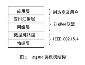
The IEEE 802.15.4 standard defines the physical layer (PHY) and data link layer (MAC); the protocols above the network layer are formulated by the ZigBee Alliance, which includes the application layer comprising the application support sub-layer (APS), ZigBee Device Object (ZDO), and application objects defined by manufacturers.
ZigBee relies on independent working nodes, using wireless communication to form star, mesh, and cluster network structures through self-organization, so the functions of each node are not entirely the same. To reduce system costs, IEEE 802.15.4 defines two types of physical device types: Full Function Device (FFD) and Reduced Function Device (RFD).
FFD nodes have controller functionality, provide data exchange, can be used as network coordinators, routing nodes, and terminal nodes, and can communicate with any type of device in the network; RFD can only be used as terminal nodes and can only communicate with FFD. RFD nodes cannot communicate with each other.
ZigBee wireless communication technology features short range, low complexity, low power consumption, low data rate, low cost, security and reliability, large network capacity, self-organization, and strong self-healing capabilities, making it widely applicable in multiple technical fields with broad market prospects.
2. Design of Smart Home Controller Based on ZigBee Technology
The network communication of the smart home system has the following characteristics:
① Small data transmission volume, no need for high transmission speed; ② Large network capacity to meet various household appliances in the home; ③ Good real-time information with short delays.
The characteristics of ZigBee technology determine that it can well meet the above requirements of the smart home network, especially with self-organization and self-healing capabilities, making this wireless communication technology an ideal communication method for smart home systems.
1. Basic Composition of Smart Home System
The smart home system can achieve interconnection and communication through GSM/GPRS/CDMA/network, ZigBee personal area network, the Internet, and community information networks. Users can control electrical appliances and lighting devices at home via mobile phones while outdoors and receive timely alerts for theft, fire, gas leaks, and other emergencies at home; at home, they can control electrical devices through a remote control. The controller also has the function of an indoor host for a visual intercom system, allowing users to view various information released by the community and send alarm signals to community security if necessary.
The system mainly consists of a smart home controller and several indoor monitoring ZigBee functional modules. The system model is shown in Figure 2. The smart home controller achieves interconnection with external facilities through two wireless communication networks, the Internet, and two wired communication lines, thus the smart home controller can also be regarded as a digital home gateway.
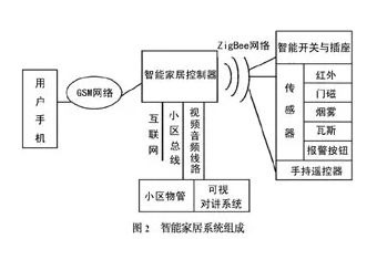
The smart home controller is equipped with a mobile phone module, which communicates with the user’s mobile phone via the GSM (GPRS, CDMA) mobile communication network, enabling bidirectional short message transmission. Users can control the power switch of household appliances and adjust brightness and speed through mobile phone short messages; the controller sends alarm signals to the user’s mobile phone in the form of short messages for theft, fire, gas leak, and other emergency alerts.
The controller is equipped with a ZigBee module, which communicates with monitoring devices in the home via ZigBee wireless network, serving as the ZigBee network coordinator (FFD). It is responsible for establishing the smart home ZigBee network, receiving commands sent by the system control center, and responding accordingly. It also sends data received from routing nodes (FFD) or terminal nodes (RFD) to the system control center.
Indoor monitoring devices can be divided into three categories based on their function: the first category includes switches and sockets, where the simplest sockets control the power switch of household appliances (such as rice cookers, water dispensers, televisions, refrigerators, air conditioners, washing machines, electric curtains, and non-dimmable lamps) through small electronic switches; more complex smart switches and sockets have adjustable output power functions for dimming chandeliers or floor lamps or adjusting the speed of fans.
The second category includes sensor products, where passive infrared sensors and door magnetic sensors are used for theft prevention, smoke sensors for fire prevention, gas sensors for gas leak detection, and manual alarm buttons for emergencies (such as sudden illness of elderly individuals). These nodes are equipped with ZigBee modules, serving as terminal nodes (RFD). The third category includes handheld remote controls, which not only control the power switches of household appliances and adjust brightness and speed but also have lighting scene setting and control functions.
If the community is equipped with a property management communication network and an intercom system, the controller also functions as the indoor host for the visual intercom system.
The LCD display on the controller can show images of visitors and allows for intercom or unlocking operations with visitors. In addition, the controller can receive various text messages sent by the community property management; in case of an emergency indoors, it can send alarm signals to the property management. The controller is equipped with an Internet interface, allowing users to control the operation of household appliances remotely via the Internet and monitor events occurring at home. The advent of the next-generation Internet will greatly support this functionality, as each appliance and the controller itself will have its static IP address, making them part of the network.
ZigBee’s cluster network combines the characteristics of star and mesh structures; in practical applications, we use the smart home controller and ZigBee sensor nodes to form a cluster network. It has good scalability, allowing users of large homes or villas to expand network coverage by adding routing nodes; for users of smaller homes, the network can become a star network by reducing routing nodes to save energy and accelerate data transmission speed.
2. Hardware Design of the Smart Home Controller
2.1 Introduction to the Smart Home Controller
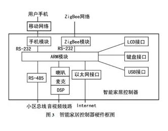
The core component of the smart home system is the smart home controller. Its block diagram is shown in Figure 3, centered around an embedded processor, consisting of a mobile phone module, a ZigBee module, and necessary auxiliary interfaces. The smart home controller is the control center of the entire smart home system, with the hardware core being the central processing unit, which is responsible for all tasks including device control, task scheduling, communication protocol conversion, data transmission and reception, and data management. Considering functionality, scalability, operating system support, and power consumption, we selected the powerful 32-bit ARM9 microprocessor S3C2410X as the main processor, with 64M NAND Flash and 64M SDRAM as memory.
In terms of human-machine interface, a 5-inch TFT LCD screen is used, equipped with a corresponding touchscreen. It can display visitor images and various information sent by the community property management, allowing users to easily input data to control various household devices. Additionally, to provide more flexible control methods, a keyboard interface is designed using the processor’s I2C bus interface, allowing for the expansion of various control and alarm methods.
The controller has two communication modules: a mobile phone module and a ZigBee module. The mobile phone module consists of a host module, SIM card interface, audio part, and RF part, using the SIM300 chip (GPRS module) produced by SIMCOM. Data transmission with ARM uses a standard RS-232 interface, and AT commands are used to operate this module for short message transmission and reception. The ZigBee module collects the operating status of various household appliances and receives various fault alarm information, transmitting data to ARM via the RS-232 interface.
The controller is equipped with an Ethernet interface, allowing users to monitor the home environment and various household appliances over the Internet using the web server established on the controller. The RS-485 interface in Figure 3 is used for communication with community property management (compatible with the existing community network; if it is a new community, the Ethernet interface can be used directly). Using MAX3232, the two USART transceivers of ARM9 form two RS-232 ports and one RS-485 port.
The audio interface uses the microprocessor’s IIS bus interface to connect to an external audio digital signal encoding chip (UDA1341TS).
The video interface uses a DSP chip from Semiconductor Manufacturing International Corporation to convert video signals into JPG file formats or binary image streams that the microprocessor can process, which are then displayed on the LCD screen.
2.2 ZigBee Module in the Smart Home Controller
The ZigBee module adopts the Full Function Device (FFD) type, which plays the role of a network coordinator in the smart home system, providing bidirectional information transmission to connect with other Reduced Function Devices (RFD) in the smart home system.
The CC2430 chip builds upon the architecture of the previous CC2420 chip, integrating ZigBee RF front end, memory, and microcontroller on a single chip. It uses an 8-bit MCU (8051), features 128KB of programmable flash memory and 8KB of RAM, and includes an analog-to-digital converter, four timers, an AES-128 co-processor, a watchdog timer, a 32kHz crystal oscillator sleep mode timer, a power-on reset circuit, a power failure detection circuit, and 21 programmable I/O pins.
The CC2430 chip is manufactured using 0118μm CMOS technology, with a current consumption of 27mA during operation; in receive and transmit modes, current consumption is below 27mA or 25mA, respectively. The ultra-short transition time between sleep mode and active mode of the CC2430 is particularly suitable for applications requiring very long battery life.
The CC2430 features two powerful US2ART communication interfaces supporting several protocols, allowing the S3C2410X processor to read or write configuration information from CC2430 and transmit or receive data through one of these communication interfaces.
The CC2430 chip integrates functions such as CRC and data integrity checks, reducing the programming workload for developers, speeding up communication, and reducing energy consumption. Additionally, the chip employs CS2MA-CA technology to avoid contention and conflicts during data transmission, further reducing unnecessary energy consumption. Therefore, the CC2430 chip has ultra-low energy consumption, with a lifespan measured in years, and is cost-effective, meeting the characteristics of sensor networks that require a large number of distributed nodes.
The controller collects the operating status of various household appliances and receives various fault alarm information via the ZigBee module through the RS-232 interface.
3. Functions of the Smart Home Controller
The operating system of the smart home controller uses an open-source embedded Linux operating system, which has been trimmed and ported to the controller hardware platform. This smart home controller integrates Linux, ARM system, mobile phone module, and ZigBee module into a complete embedded system, easily achieving wireless connections among multiple nodes within the home using ZigBee technology. The functions of the smart home controller include:
(1) Utilizing a 32-bit embedded RISC processor based on ARM architecture and an open-source embedded Linux operating system;
(2) Serving as the control center of the smart home control system and the gateway of the information appliance platform in the home system;
(3) In the event of theft or illness, pressing the emergency button automatically sends an alarm to the management center;
(4) Configured on a household basis, using the LCD screen to display community notifications, system operational status, and data;
(5) Monitoring various fault alarm data (fire, gas leaks, etc.) using ZigBee sensor nodes, and automatically sending alerts to the user or community management center via the mobile phone module;
(6) Communicating with the community management center via Ethernet (or RS-485);
(7) Communicating with various sub-nodes in the home system through the wireless ZigBee module on the controller, controlling various household appliances accordingly;
(8) Allowing users to remotely monitor various household devices in the home via the Internet.
The smart home controller collects the operating status of various household appliances through the ZigBee module and stores various fault alarm data in a database; it prioritizes fault alarms and automatically sends short messages to the user’s mobile phone or community property management, while real-time data is stored in the database for further analysis and statistics.
In this context, the database serves as middleware connecting the front and back ends, storing status data for remote monitoring and local LCD display, while receiving input from browsers and local keyboards, with the communication program and CGI program managing the transmission of control commands and the upload of operational status; the database also needs to implement fault analysis, statistics, and querying. In this system design, we use the embedded database SQLite to meet the requirements for remote control data transmission and data sharing.
The software of the controller is mainly divided into four modules: the communication program with the data acquisition interface, the fault alarm program, the local human-computer interaction program, and the remote control program. To allow users to control the smart home network via the Internet through a browser, a web server needs to be set up on the controller (digital home gateway) to communicate with users and call the backend CGI program through the CGI interface.
The CGI program establishes a connection between the web server and control program, invoking specific control programs to perform designated operations on the internal nodes of the smart home network. It monitors the network, allowing users to know the status of devices within the network at any time and control various devices within the network. Network monitoring is also very important in home networks, enabling users to stay informed about the network’s status, such as device join/leave events, equipment failures, etc.
3. Conclusion
ZigBee technology fills the gap in the low-cost, low-power, and low-speed wireless communication market. The hardware of the smart home controller consists of an advanced ARM9 embedded system, a mobile phone module, and a ZigBee module; the operating system adopts embedded Linux, and the home network utilizes ZigBee wireless network, ensuring good security and comprehensive system functionality, capable of adapting to future developments in smart homes.
– END –
◆ ◆ ◆
Recommended Reading
Meituan Penalized for Monopoly: Forced Merchants to Choose One; AI Giants Win 2018 Turing Award; Human Sixth Sense Confirmed for the First Time
Shenzhen Airlines App Hijacks WeChat; Apple News Faces Various Crashes on Launch Day; Huawei P30 “Telescope Phone” Officially Released
Breaking! Apple Undergoes Largest Transformation: Apple Card Support, Four New Products Unveiled
Didi Responds to Ride-Hailing Driver’s Murder; New iPhone May Support Bidirectional Wireless Charging; Alibaba Acquires Israeli AR Company