Introduction
With the advancement of technology and the rapid development of social productivity, the robotics industry has flourished, among which quadruped robots have developed quickly and are widely used. Quadruped robots are a highly integrated research product, primarily driven by mechatronic technology and incorporating knowledge from various fields such as microcontroller technology, hydraulics, sensors, and more. Quadruped bionic robots possess high mobility, strong load capacity, and adaptability, making them suitable for applications in material transportation, rescue operations, and more, thus having a broad prospect. Due to the high costs associated with manufacturing motor dogs, designing and building a servo dog independently to study the gait algorithms of quadruped robots is a cost-effective and meaningful endeavor. (Here are a few symbolic phrases copied and pasted; a sense of ceremony is still necessary.)
This article will detail the blogger’s DIY project of a 12-degree-of-freedom servo dog. It will cover everything from initial structural design, servo selection, MATLAB simulations of gait algorithms, theoretical waveform analysis of various movements such as trot, back, turn_left, turn_right, mark_time, and the entire process of programming the STM32F103ZET6 main control program, to the final walking of the robot dog. (No more nonsense, pure dry goods presented, let’s dig in!)
1. Understanding Quadruped Structures
By reviewing relevant materials, we categorize quadruped types into several types based on the mechanical structure of each leg, dividing them into parallel mechanism legs and serial mechanism legs. According to the joint configuration of the four legs, we can further divide them into four structural layouts: front elbow and rear knee, front knee and rear elbow, front and rear elbow, and front and rear knee.
Principle: Each leg consists of a double-degree-of-freedom five-bar linkage mechanism made up of two motors in parallel. By rotating the two motors at different angles, we can achieve movement at any point of the foot end. A typical structure is the quadruped used in the 2019 Robocon competition at Wuhan University, as shown in the figure.
Advantages: The torque selection for motors is not high, allowing for low torque and high jumping capability. The rigidity of the linkages is high, the mass is low, and the response speed is fast. Disadvantages: The degrees of freedom in the legs are relatively few, making it difficult to add more degrees of freedom structurally, which can hinder agility in certain situations. The connection issues of the linkages need to be resolved, and safety is low.
1.1.2 Serial Mechanism
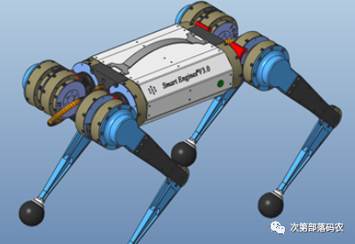
Principle: Each leg consists of a double-degree-of-freedom leg made up of two motors in series. By rotating the two motors at different angles, we can achieve independent rotation of the thigh and calf, meaning the rotation of the thigh motor does not affect the rotation of the calf motor, and vice versa. A structural example is the open-source quadruped model from MIT, as shown in the figure.
Advantages: The appearance closely resembles the physiological structure of a “dog”, with a rich variety of structural forms, making it easier to add degrees of freedom. The structure is flexible and simple, with high reliability and safety. Disadvantages: High torque selection requirements for motors, needing motors with large torque, and the motors generally have a large reduction ratio, which can lead to certain gap issues in ordinary reduction gears.
1.2 Quadruped Joint Configuration
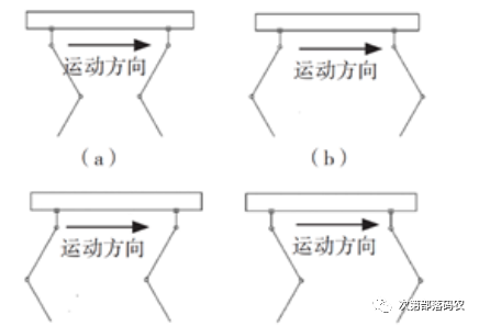
The advantage of quadruped robots is their high flexibility and good stability. Therefore, it is crucial to consider their joint configuration in advance during the design phase to find the most suitable structure to avoid affecting their movement flexibility and stability. Currently, the common bionic structures for quadrupeds are the following four types: (a) front elbow and rear knee, (b) front knee and rear elbow, (c) front and rear elbow, and (d) front and rear knee, as shown in the figure. These four structures are common bionic structures, each with its advantages and disadvantages, and each can design quadruped robots with different performances.
2. Structural Scheme Selection and Servo Selection
2.1 Selection of Parallel and Serial Mechanisms
Based on design requirements, appearance, ease of making the quadruped, and cost issues, there is not much difference in difficulty between the two in terms of structure and algorithms. From the perspective of flexibility and existing mature solutions, we prioritize the 12-degree-of-freedom serial quadruped structure. For this reason, we considered multiple schemes.
Scheme 1: As shown in the figure below, this model is one we previously prepared to design and manufacture a motor dog. It adopts a synchronous belt-driven serial quadruped structure, but due to insufficient motor torque, it leads to difficulties in standing and walking. We also discovered some defects of the synchronous belt; the tensioning issue is complex and can easily skip teeth and slip under high-load conditions. Additionally, its response speed and precision may not be as good as linkages or lead screws. The advantage is that the motor is mounted near the hip joint, significantly reducing the leg’s mass, thus speeding up its response time.
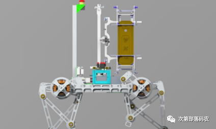
Scheme 2: As shown in the figure below, this model is the Northeastern University Robocon quadruped model from 2019. This quadruped uses lead screw transmission, which has high transmission precision, but based on the existing motor and lead screw parameters, the disadvantage of lead screw transmission is its slower transmission speed, which may make it difficult to achieve jumping actions.
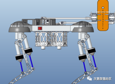
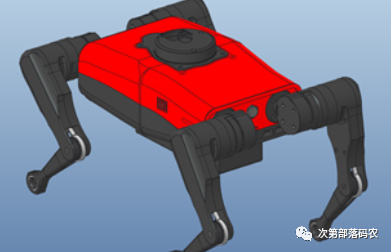
Scheme 3: As shown in the figure below, this model is the quadruped model from Yushu Technology, which uses a linkage structure for its legs. The motor is mounted near the hip joint, significantly reducing the leg’s mass, thus speeding up its response time. Additionally, the linkage has strong rigidity and does not experience skipping teeth.
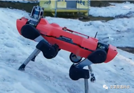
Scheme 4: As shown in Figure 2.6, this model is a quadruped robot developed by ETH Zurich. Its structural feature is that the motors are mounted at the joints, making installation and maintenance simple, but the leg’s inertia greatly affects the leg’s response speed, thus impacting its agility.
Based on the above schemes, we adopt a linkage serial structure quadruped robot, characterized by its high strength, low mass of legs, fast response speed, high precision, and ease of installation and disassembly.
2.2 Selection of Quadruped Joint Configuration
Through observation and the research of many predecessors on the structure of quadruped robots, we find that the front and rear knee structure is more in line with the leg structure of animals such as cheetahs and dogs. This structure has an elegant appearance and is relatively flexible, making it easier to achieve complex movements such as jumping and backflips. Therefore, we adopt this structure for design verification.
2.3 Motor Selection (Suggestions for those with economic foundations)
The plan has always been to create a motor dog. After multiple research comparisons and data analysis, we finally selected a particularly suitable motor. Due to funding and communication issues with the teacher, we ultimately chose to first attempt to make a servo dog. However, regarding the previous process of motor selection, I will share it for reference.
For motor selection, a 12-degree-of-freedom quadruped means a large number of motors, so we prioritize motors that integrate encoders and drives to reduce unnecessary components’ space and weight issues. Next, we consider the motor’s torque, power, speed, etc. We estimate the quadruped’s mass to be about 16 kg, with both the thigh and calf lengths being 200 mm. The maximum torque required for the quadruped to rise from a lying position is calculated to be about 8 Nm. The hip joint motor can use a motor with relatively low torque, so we plan to use the DJI 3508 motor with a gearbox as the hip joint motor.
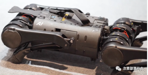
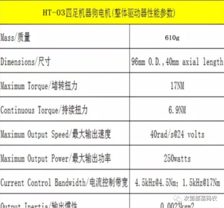
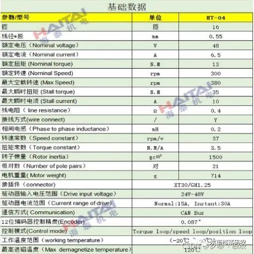
From Yushu Technology’s A1 robot dog, we learned that the motor torque can reach 100 Nm, with a speed of 20 r/min. However, the company only sells motors with a torque of around 30 Nm and requires a minimum order of 12, with a long lead time. Later, we saw that MIT’s quadruped used the Hitec HT-03 motor, which has a stall torque of 17 Nm. Therefore, we checked the Hitec HT-03 motor and unexpectedly found a more suitable motor for quadrupeds—the HT-04 motor, which has a stall torque of 35 Nm and a speed of 300 r/min, making it more than capable of performing basic walking and high-difficulty operations such as jumping and flipping.
Hitec Motor: HT-03 Motor Parameters:
HT-04 Motor Parameters:
2.4 Servo Selection
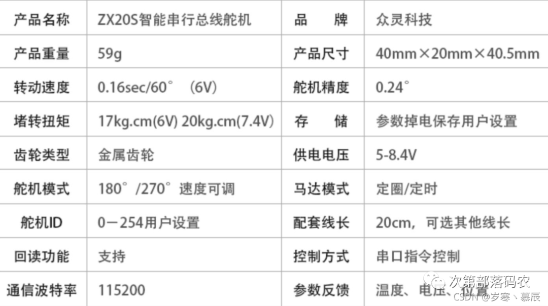
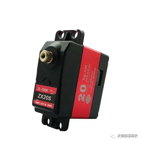
Next, we will use a high-torque, well-performing intelligent serial bus servo (dual-axis) from Zhongling Technology for the final physical production. Below are the specific parameters of this servo, and after data analysis, it supports walking without any issues. Due to the urgency of studying quadruped gait algorithms and limited time and funding, we will temporarily use this servo.
3. Structural Design 3D Modeling and Finite Element Analysis
The overall plan uses 3D printing for part processing, with PLA as the material. Modeling is first done using Creo, followed by topology optimization and structural load analysis using Altair Inspire and Creo generative design to achieve better optimization methods. Based on the analysis results, the model is further modified using modeling software Creo. The specific process is as follows:
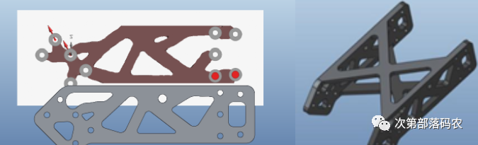
3.1 Calf Optimization Process (Topology Optimization)
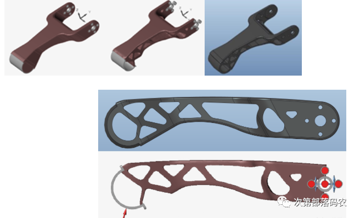
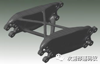
3.2 Thigh Optimization Process (Topology + Generative Optimization)
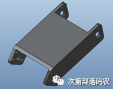
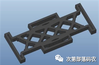
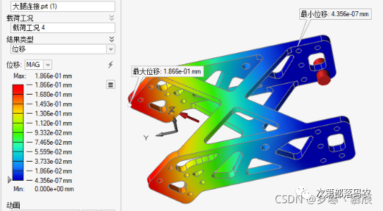
3.3 Body Optimization (Generative Design)
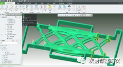
3.4 Finite Element Analysis
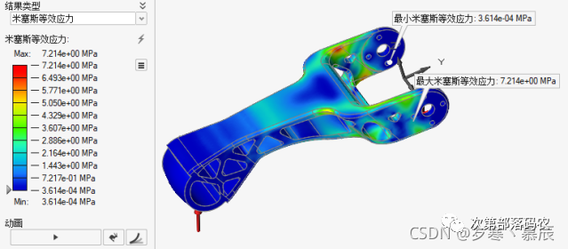
Through ANSYS Workbench, finite element analysis can yield optimization results that meet normal working requirements. The results are compared with finite element analysis from Altair Inspire, showing similar results from both software (demonstrated here using the calf and thigh as examples), and the safety factors analyzed are all far above 1.5, indicating that this design scheme is reasonable.
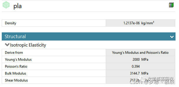
Material Property Analysis:
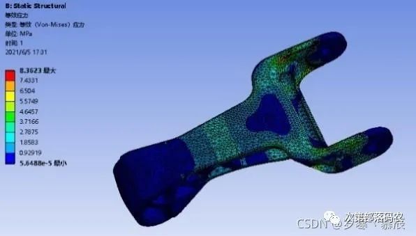
Calf Stress Distribution Cloud Map (Ansys):
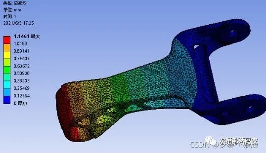
Calf Deformation Cloud Map (Ansys):
Calf Stress Distribution Cloud Map (Inspire):
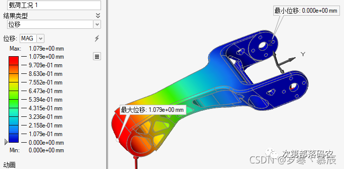
Calf Deformation Cloud Map (Inspire):
Thigh Stress Distribution Cloud Map (Inspire):
Thigh Deformation Cloud Map (Inspire):
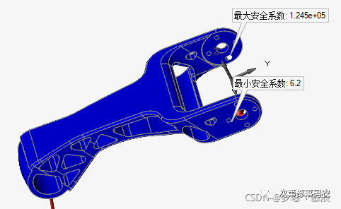
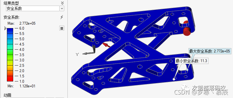
3.5 Safety Factor Analysis
Calf Safety Factor:
Thigh Safety Factor:
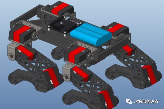
3.6 Three-Dimensional Design Diagram
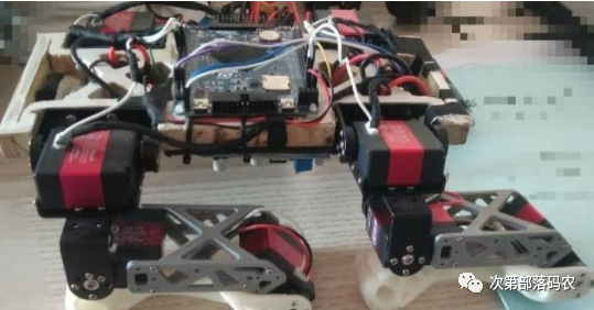
3.7 Physical Display

3.8 Physical Walking Demonstration