Part Three: Mechanical Response and Fluid Motion——The Art of Flow Measurement
Flow measurement is one of the most challenging tasks in industrial processes, with an error margin of±0.05% being world-class. Due to the complexity of fluid properties and the variability of flow conditions, no single flow meter can be suitable for all operating conditions.
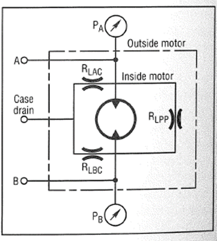
1. Volumetric Flow Meters: Accounting for“Volume”: The Principle: Like a precision hydraulic motor, it continuously divides the fluid into known volumes of“small units” and measures the total volume by counting these units. The instantaneous flow rate is determined by measuring the counting frequency.Common Types: Oval gear, Roots (lobe), Rotary piston, Scraper, and Screw type.Advantages: High accuracy, wide range, unaffected by fluid viscosity (within a certain range) and flow state, making it one of the most accurate flow meters.Disadvantages: Contains moving parts, has significant pressure loss, is sensitive to solid particles in the medium, and requires regular maintenance and calibration.
Example: Trade Settlement between Gas Stations and Oil Depots At the core of the fuel dispenser and the shipping end of the oil depot, volumetric flow meters (such as rotary gear type) are the legal trade settlement tools. Its high accuracy and repeatability directly relate to the economic interests of both parties. The fluid drives the internal piston or gear to rotate, and the volume of fluid corresponding to each rotation is fixed and calibrated. By counting the number of rotations using optical or magnetic sensors, the total volume can be accurately obtained. This is a typical application of volumetric flow meters in high-precision measurement scenarios. National metrology departments regularly conduct mandatory inspections on these flow meters to ensure their accuracy is within the legally permitted error range.
2. Turbine Flow Meters: The Tachometer of Fluid Mechanics
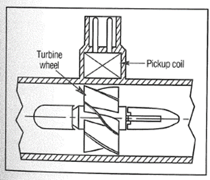
Principle: An axial flow turbine is placed at the center of the fluid channel. When the fluid flows, it impacts the turbine blades, generating a torque that causes it to rotate. Within a certain flow range, the turbine’s rotational speed is proportional to the average flow velocity of the fluid (i.e., volumetric flow). Typically, the frequency of the turbine blades passing is detected by installing a magnetic or inductive proximity sensor on the housing, where the frequency f represents the flow rate Q.Calibration Curve (K Factor): The soul of a turbine flow meter is itsK factor curve, which is the relationship curve between the number of pulses/ unit volume and flow rate/ viscosity in ideal laminar flow conditions, K factor is constant. However, over a wider range, it is a curve that needs to be corrected based on the actual fluid viscosity. High-quality turbine flow meters provide detailedK factor curves or fitting formulas.Example: Aviation Fuel Flow Measurement In the aircraft fuel system, it is necessary to accurately know the fuel consumption of the engine. Turbine flow meters are widely used due to their compact structure, fast response, and moderate accuracy . It is installed on the fuel supply pipeline, outputting a pulse frequency proportional to the fuel flow rate in real-time, allowing the avionics computer to calculate the remaining range and engine efficiency. The choice of materials for the bearings and turbine is crucial, as they must withstand the lubricating properties of aviation kerosene and possible trace impurities over the long term. Modern aviation turbine flow meters can even detect the presence of bubbles in the fuel by analyzing the minute fluctuations in turbine rotation.
3. Differential Pressure Flow Meters: Application of Bernoulli’s Equation
This is the oldest and most common flow measurement method in industry, based on Bernoulli’s equation of fluid energy conservation. It estimates flow by creating a local resistance in the pipeline and measuring the pressure difference before and after it.
Principle: A throttling element (such as an orifice plate, Venturi tube, or wedge) is installed in the pipeline, creating a pressure difference ΔP when the fluid flows through it. This pressure difference ΔP is proportional to the square of the flow rate Q ∝√ΔP.Core Challenge: The output is square root related to flow, which has low sensitivity at low flow rates. A square root operation is needed to obtain a linear flow signal. In modern smart transmitters, this is easily achieved through built-in microprocessors.Common Types:Standard Orifice Plate: Simple structure, low cost, but high pressure loss, and high requirements for the straight pipe section upstream. Due to its high standardization, it is widely used in steam, gas, and liquid measurements.Venturi Tube: Low pressure loss, more suitable for large flow measurements, but larger in size and higher in cost. Commonly used for flow monitoring in water plants and large pumping stations.Laminar Flow Element: Based on Poiseuille’s law, ΔP ∝ Q is linear! It forces the fluid to be in a laminar state through a bundle of dense capillaries or flow channels. The advantages are linearity and fast response, but it is prone to clogging, and pressure loss varies with viscosity. It is mainly used for small flow measurements of clean gases.
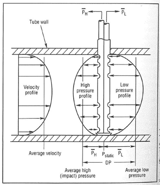
Example: Main Steam Flow Measurement in Power Plants In thermal power plants, measuring the flow of high-temperature, high-pressure steam entering the turbine is key to calculating the efficiency and load of the unit. Standard Orifice Plates are the preferred choice for this application due to their robust structure, ability to withstand high temperatures and pressures, and established international standards (such as ISO 5167 ). By measuring the differential pressure ΔP before and after the orifice plate, and compensating for the temperature and pressure of the steam (using the ideal gas state equation or steam property tables), the mass flow rate of the steam can be accurately calculated. Despite the non-linearity and straight pipe section requirements, its reliability and standardization have made it enduring in this field. A complete measurement system includes the orifice plate, pressure tapping points, pressure pipes, a three-valve group, and a differential pressure transmitter, all of which require professional knowledge for installation and maintenance.
4. Thermal Flow Meters: The Speed of Heat Transfer
Principle: Constant Temperature Difference Method: Two temperature probes, one heated (T_H), and one measuring the fluid’s body temperature (T_F). By controlling the heating power P through a feedback circuit, the temperature difference (T_H – T_F) is kept constant. Thus, the heating power P is proportional to the mass flow rate of the fluid Q_m . The faster the fluid flow, the more heat is carried away, requiring more power to maintain the temperature difference.Constant Power Method: A constant power is supplied to the heater, and its temperature T_H is measured. The faster the flow rate, T_H decreases. By measuring (T_H – T_F) , flow can be inferred.Advantages: Direct measurement of mass flow rate without the need for temperature and pressure compensation; no moving parts, minimal pressure loss; fast response; very suitable for low flow rate gas measurements.Disadvantages: Measurement accuracy is affected by gas composition (due to different specific heat capacities); sensitive to pipeline vibrations; not suitable for liquids or dirty gases.
Example: Ultra-Pure Gas Monitoring in Semiconductor Factories In chip manufacturing, it is necessary to precisely control the flow of various ultra-pure specialty gases (such as silane and phosphine) delivered to the process reaction chamber. These gas flows are typically very small (on the order of milliliters per minute), and any contamination or pressure loss can affect chip yield. Thermal Mass Flow Controllers
are the absolute leaders in this field. They directly output signals proportional to mass flow rate without the need for temperature and pressure compensation, with fast response and extremely high control accuracy. Their internal capillary sensing tubes and precision control valves ensure stable and precise gas flow delivery to the reaction chamber, which is key to ensuring uniformity in chip film thickness and electrical performance. The entire gas panel system may integrate dozens of such MFCs , precisely coordinated by a central control system.
5. Coriolis Mass Flow Meters: Direct Mass Measurement
Principle: Based on the Coriolis force effect. The fluid flows through one or more vibrating U-shaped, Ω-shaped, or straight tubes. When the fluid flows within the vibrating tube, a Coriolis force proportional to the mass flow rate is generated, causing the tube to twist from its original vibration. Displacement sensors installed at the inlet and outlet of the vibrating tube detect this phase difference (Δt) , where Δt is directly proportional to the fluid’s mass flow rate Q_m . At the same time, the vibration frequency of the tube is related to the density ρ of the fluid. By measuring the frequency, the density value can be obtained simultaneously.Huge Advantages: Able to simultaneously, directly, and accurately measure mass flow rate, density, and temperature , allowing for the calculation of volumetric flow, solid content, concentration, etc. It is currently the only industrial flow meter that can directly measure mass flow rate (without relying on other parameters for conversion).Disadvantages: High initial investment cost; sensitive to installation stress, requiring sufficient installation space to ensure that pipeline stress does not affect measurement; relatively high pressure loss for larger diameters; not suitable for very low flow conditions.
Example: Ingredient and Filling in the Food and Beverage Industry In the production of beverages such as Coca-Cola and beer, it is necessary to mix syrup, purified water, CO₂ , etc., in precise proportions. Coriolis mass flow meters are the perfect tool for achieving this goal. They directly measure the mass of each material, unaffected by fluid bubbles or viscosity changes. For example, when mixing syrup, they ensure that the sweetness of every bottle of beverage is absolutely consistent. Furthermore, in crude oil trading, chemical loading, and other scenarios requiring precise mass settlement, Coriolis flow meters have also become the preferred choice. In the oil industry, Coriolis flow meters can simultaneously measure the instantaneous mass flow rate and density of crude oil, thus providing a direct basis for trade pricing by calculating its API gravity in real-time.
Part Four: Advanced and Special Sensor Principles
1. Ultrasonic Sensing: Utilizing Sound Echoes
Ultrasonic Position Sensors (such as Magnetostrictive):Principle: Taking magnetostrictive displacement sensors as an example. A waveguide made of magnetostrictive material passes through a protective tube. At the sensor head, a current pulse generator sends an inquiry pulse to the waveguide, which propagates along it. A position magnet (fixed on the moving object) is fitted outside the protective tube. When the annular magnetic field generated by the current pulse meets the permanent magnetic field of the position magnet, according to the Wiedemann Effect, the waveguide experiences an instantaneous torsional strain. This strain pulse propagates to the sensor head at the speed of sound. A pickup device at the head detects this return pulse. By accurately measuring the time Δt from the emission of the inquiry pulse to the reception of the return pulse, the position of the magnet can be calculated S = (v * Δt) / 2 (where v is the speed of sound in the waveguide).Example: Absolute Position Feedback of Large Hydraulic Cylinders In large hydraulic cylinders of injection molding machines, presses, and other equipment, it is necessary to know the precise absolute position of the piston. Magnetostrictive displacement sensors can be directly installed in the hollow interior of the hydraulic cylinder’s piston rod. The position magnet is fixed on the piston. This built-in design is compact, completely non-contact, and wear-free, providing absolute position output, extremely high resolution , and is unaffected by oil contamination or vibrations, making it standard in high-end hydraulic position servo systems. In steel mill hydraulic cylinders, they endure extreme shocks and vibrations while still providing stable and reliable position feedback.Ultrasonic Flow Meters:Time Difference Method: A pair of ultrasonic transducers A and B are installed diagonally on both sides of the pipeline. The time taken for ultrasonic waves to travel from A to B (downstream) and from B to A (upstream) is measured to determine the time difference Δt . This time difference Δt is proportional to the average flow velocity of the fluid. It has high accuracy and is suitable for clean liquids.Doppler Method: Suitable for fluids containing bubbles or particles. The transducer emits ultrasonic waves at a fixed frequency, and the waves reflected back from the suspended particles in the fluid will experience a frequency shift (Doppler effect), with the frequency shift proportional to the speed of the suspended particles (i.e., fluid flow velocity). It is suitable for impure fluids such as sewage and slurries.Example: Flow Monitoring and Leak Detection in Urban Water Supply Networks Drilling holes to install flow meters on existing urban water supply mains is both difficult and expensive. Clamp-on Time Difference Ultrasonic Flow Meters have emerged as a solution. Simply clamping two sensors on the outer wall of the pipeline allows for flow measurement, completely unobstructed, with no pressure loss . This brings revolutionary convenience for monitoring large diameter flow, locating pipeline leaks, and regional measurement management. Late at night, when water usage is very low, if a certain area still detects a continuous small flow, it may indicate a hidden leak in the pipeline. By analyzing data from multiple monitoring points, leak points can be accurately located, greatly reducing water resource waste.
2. Magnetostrictive: Direct Dialogue between Magnetic Fields and Strain
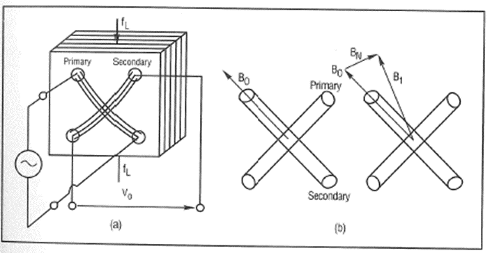
- Principle: Certain ferromagnetic materials (such as iron-cobalt alloys) undergo slight changes in physical dimensions under the influence of a magnetic field, and conversely, applying stress also alters their magnetization strength.
- Example (besides displacement sensors): Magnetostrictive Force Sensors
- As shown in the figure, force sensors can be made using the magnetostrictive effect. The primary and secondary coils are arranged perpendicularly in space. When unloaded, the magnetic flux generated by the primary coil does not pass through the secondary coil. When force is applied, the magnetic permeability of the magnetostrictive material changes in the direction of the force, causing part of the magnetic flux to deflect and pass through the secondary coil, inducing a voltage. This voltage is proportional to the applied force. This sensor structure is robust, with strong overload capacity, and can be used for force monitoring in harsh industrial environments such as injection molding machines and presses.
Conclusion
The physical sensing world presented in this article is a treasure trove of creative thinking. From the use of solid elasticity in Bourdon tubes to various flow meters based on fluid mechanics principles; from bimetallic strips utilizing thermal expansion to Coriolis flow meters based on quantum physical effects; from traditional mechanical measurements to advanced ultrasonic and magnetostrictive technologies—— each principle is a clever application of human wisdom to natural laws.
The Art of Choosing Sensors: When faced with a specific measurement task, engineers need to consider comprehensively:
The Measured Object: Is it pressure, flow, force, temperature, or position?Operating Conditions: What is the medium (corrosiveness, cleanliness, phase)? What are the temperature and pressure ranges? What are the environmental vibrations and hazards?Performance Requirements: What are the accuracy, response speed, and stability requirements?Economics and Maintenance: Initial investment, installation costs, long-term maintenance costs, and calibration cycles.Output and Integration: Is a simulated signal or digital communication needed? How to integrate with existing control systems?
Integration and Future of Sensing Technology: Modern sensors are developing towards multifunctionality, intelligence, and networking .
Multifunctionality: A Coriolis flow meter outputs mass flow, density, and temperature simultaneously; a smart pressure transmitter can measure absolute pressure, gauge pressure, and differential pressure simultaneously.Intelligence: Sensors with built-in microprocessors have self-diagnosis (such as detecting blockages, aging, wiring errors), self-compensation (temperature, non-linearity compensation), and self-calibration functions. IO-Link and other communication protocols make parameter settings, data access, and fault diagnosis unprecedentedly convenient.Networking: Sensors become nodes of the Industrial Internet of Things, uploading data to the cloud via wired or wireless means, enabling massive data collection and analysis, providing a data foundation for predictive maintenance, energy management, and process optimization.MEMS Technology: Micro-electromechanical systems technology will continue to drive the miniaturization, low power consumption, and low cost of sensors, giving rise to more innovative products for consumer electronics, medical health, and the Internet of Things.
Conclusion
In this data-driven era, sensors serve as the bridge between the physical and digital worlds, and their importance cannot be overstated. The various sensing principles introduced in this chapter, from mechanical deformation to energy conversion, provide us with a rich toolbox for solving real-world measurement problems. By deeply understanding these principles, we can not only select the most suitable sensors for specific applications but also gain insights into the limitations and potentials of different sensing technologies, thereby designing more robust, precise, and intelligent measurement control systems. From basic mechanical instruments that ensure industrial safety to advanced process analysis instruments for cutting-edge manufacturing, sensing technology remains the cornerstone of technological advancement and industrial upgrading. Mastering its principles is the key to unlocking a smart future.