Basic Knowledge of Common Sensors

1
Basic Knowledge of Common Sensors
The definition of a sensor is: “a device or apparatus that can sense the specified measurement and convert it into a usable signal according to certain rules, usually composed of a sensitive element and a conversion element.” A sensor is a detection device that can sense the information being measured and convert the detected information into an electrical signal or other required form of information output according to certain rules, to meet the requirements for information transmission, processing, storage, display, recording, and control. It is a primary link in achieving automatic detection and automatic control.
2
Classification of Sensors
Currently, there are three commonly used classifications of sensors:
1. According to the physical quantity of the sensor, it can be divided into displacement, force, speed, temperature, flow, gas composition, etc.
2. According to the working principle of the sensor, it can be divided into resistance, capacitance, inductance, voltage, Hall effect, photoelectric, grating, thermocouple, etc.
3. According to the nature of the output signal of the sensor, it can be divided into: switch-type sensors with outputs as switching quantities (“1” and “0” or “on” and “off”); analog sensors; digital sensors with pulse or code outputs.
About Sensor Classification
1. According to the measured physical quantity: such as force, pressure, displacement, temperature, angle sensors, etc.
2. According to the working principle of the sensor: such as strain sensors, piezoelectric sensors, piezoresistive sensors, inductive sensors, capacitive sensors, photoelectric sensors, etc.
3. According to the way the sensor converts energy:
(1) Energy conversion type: such as piezoelectric, thermocouple, photoelectric sensors, etc.
(2) Energy control type: such as resistive, inductive, Hall effect sensors, as well as thermistors, photoconductive resistors, and humidity-sensitive resistors.
4. According to the working mechanism of the sensor:
(1) Structural type: such as inductive and capacitive sensors.
(2) Physical property type: such as piezoelectric, photoelectric, and various semiconductor sensors.
5. According to the form of output signal of the sensor:
(1) Analog type: the sensor outputs an analog voltage.
(2) Digital type: the sensor outputs a digital quantity, such as encoder-type sensors.
3
Static Characteristics of Sensors
The static characteristics of a sensor refer to the relationship between the output quantity and the input quantity for static input signals. Because both the input and output quantities are independent of time, their relationship, that is, the static characteristics of the sensor, can be described by an algebraic equation that does not contain time variables, or by plotting the characteristic curve with the input quantity as the horizontal coordinate and the corresponding output quantity as the vertical coordinate. The main parameters characterizing the static characteristics of the sensor include: linearity, sensitivity, resolution, and hysteresis.
4
Dynamic Characteristics of Sensors
The so-called dynamic characteristics refer to the characteristics of the sensor’s output when the input changes. In practical work, the dynamic characteristics of the sensor are often expressed by its response to certain standard input signals. This is because the response of the sensor to standard input signals can be easily obtained by experimental methods, and there is a certain relationship between its response to standard input signals and its response to arbitrary input signals; often knowing the former allows one to infer the latter. The most commonly used standard input signals are step signals and sine signals, so the dynamic characteristics of the sensor are also often expressed in terms of step response and frequency response.
5
Linearity of Sensors
In general, the actual static characteristic output of a sensor is a curve rather than a straight line. In practical work, to make the instrument have uniform scale readings, a fitting straight line is often used to approximate the actual characteristic curve; linearity (non-linear error) is a performance index of this degree of approximation.
There are various methods for selecting the fitting straight line. For example, connecting the theoretical straight line that links the zero input and full-scale output points as the fitting straight line; or using the theoretical straight line whose sum of the squares of deviations from each point on the characteristic curve is minimized as the fitting straight line, this fitting straight line is called the least squares fitting straight line.
6
Sensitivity of Sensors
Sensitivity refers to the ratio of the change in output quantity Δy of the sensor to the change in input quantity Δx under steady-state working conditions.
It is the slope of the output-input characteristic curve. If there is a linear relationship between the output and input of the sensor, then the sensitivity S is a constant. Otherwise, it will vary with changes in the input quantity.
The dimension of sensitivity is the ratio of the dimensions of output and input quantities. For example, in a displacement sensor, when the displacement changes by 1mm, the output voltage changes by 200mV, then its sensitivity should be expressed as 200mV/mm.
When the dimensions of the output and input quantities of the sensor are the same, sensitivity can be understood as the amplification factor.
Improving sensitivity can achieve higher measurement accuracy. However, the higher the sensitivity, the narrower the measurement range, and the stability is often poorer.
7
Hysteresis Characteristics of Sensors
The hysteresis characteristic characterizes the degree of inconsistency between the output-input characteristic curves during the forward (input quantity increases) and reverse (input quantity decreases) strokes, usually expressed as the maximum difference ΔMAX between these two curves as a percentage of full-scale output F·S.
The hysteresis can be caused by the energy absorption of the internal components of the sensor.
Resistive Sensors
Resistive sensors are devices that convert measured quantities, such as displacement, deformation, force, acceleration, humidity, temperature, etc., into resistance values. The main types include resistive strain sensors, piezoresistive sensors, thermistors, thermosensitive, gas-sensitive, and humidity-sensitive resistive sensors.
Resistive Strain Sensors
The resistive strain gauge in the sensor has a metal strain effect, meaning it generates mechanical deformation under external force, causing the resistance value to change accordingly. Resistive strain gauges mainly include metal and semiconductor types, with metal strain gauges categorized into wire type, foil type, and thin-film type. Semiconductor strain gauges have advantages such as high sensitivity (usually dozens of times that of wire and foil types) and low transverse effect.
Piezoresistive Sensors
Piezoresistive sensors are devices made based on the piezoresistive effect of semiconductor materials, formed on the substrate of semiconductor materials through diffused resistors. The substrate can directly serve as the measuring sensing element, and the diffused resistors are connected in a bridge configuration within the substrate. When the substrate is subjected to external force and deforms, the values of each resistor will change, resulting in an unbalanced output from the bridge.
The substrate (or diaphragm) material used for piezoresistive sensors is mainly silicon and germanium, with silicon piezoresistive sensors made from sensitive materials gaining increasing attention, particularly for measuring pressure and speed, where solid-state piezoresistive sensors are most commonly used.
Thermistors
Thermistors primarily utilize the property of resistance changing with temperature to measure temperature and related parameters. This type of sensor is more suitable for situations where high temperature detection accuracy is required. Currently, the most widely used thermistor materials are platinum, copper, and nickel, which have a large temperature coefficient of resistance, good linearity, stable performance, a wide operating temperature range, and are easy to process. They are used to measure temperatures in the range of -200℃ to +500℃.
Hall Sensors
Hall sensors are magnetic sensors based on the Hall effect. When an object carrying current is placed in a magnetic field, if the direction of the current is perpendicular to the direction of the magnetic field, a transverse potential difference will be generated in a direction perpendicular to both the magnetic field and the current direction. This phenomenon is called the Hall effect, and the resulting potential difference is called the Hall voltage.
Hall devices are made from semiconductor materials that produce a significant Hall effect. As the magnetic-electric conversion element in Hall sensors, they can be used for electromagnetic measurements, such as measuring magnetic fields, currents, electric power, and other magnetic physical quantities and electricity. Hall sensors can also utilize magnetic fields as mediums to achieve non-contact measurements of many physical quantities.
By converting non-electric quantities such as force, displacement, vibration, acceleration, speed, and flow, they are widely used in industrial, transportation, communication, automatic control, and household electrical appliances.
According to the function of Hall devices, they can be divided into: Hall linear devices and Hall switch devices. The former outputs analog quantities, while the latter outputs digital quantities.
Based on the nature of the objects being detected, their applications can be divided into: direct applications and indirect applications. The former directly detects the magnetic field or magnetic characteristics of the object being tested, while the latter detects the artificially set magnetic field on the object being tested, using this magnetic field as the carrier of the information being detected, thus converting many non-electric and non-magnetic physical quantities such as force, torque, pressure, stress, position, displacement, speed, acceleration, angle, angular velocity, rotation number, rotational speed, and the time of changes in working state into electrical quantities for detection and control.
Hall devices can be categorized into: Hall elements and Hall integrated circuits. The former is a simple Hall chip, which often requires amplifying the obtained Hall voltage during use. The latter integrates the Hall chip and its signal processing circuit on the same chip.
Hall elements can be made from various semiconductor materials, such as Ge, Si, InSb, GaAs, InAs, InAsP, and multilayer semiconductor heterostructures, quantum well materials, etc.
Hall Switch Circuits
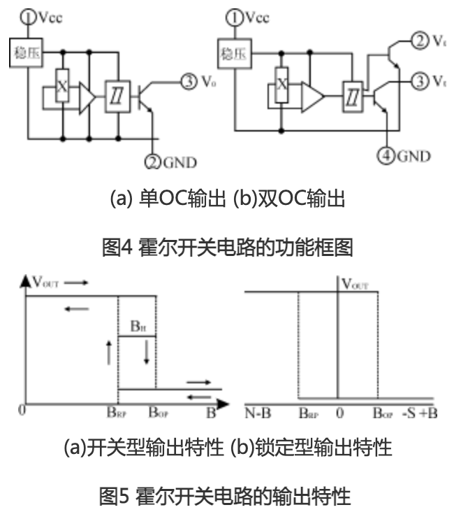
Hall switch circuits, also known as Hall digital circuits, consist of a voltage regulator, Hall chip, differential amplifier, Schmitt trigger, and output stage. Under the influence of an external magnetic field, when the magnetic induction intensity exceeds the conduction threshold BOP, the Hall circuit output tube conducts, outputting a low level. As B increases, it remains in the conducting state. If the external magnetic field’s B value decreases to BRP, the output tube turns off, outputting a high level. We refer to BOP as the working point and BRP as the release point, with BOP – BRP = BH referred to as the hysteresis. The presence of hysteresis enhances the anti-interference capability of the switch circuit. The functional framework of the Hall switch circuit is shown in Figure 4. Figure 4(a) shows the open-collector (OC) output, and (b) shows the dual output. Their output characteristics are shown in Figure 5, with Figure 5(a) showing the output characteristics of a normal Hall switch, and (b) showing those of a latching Hall switch.
Basic Knowledge of Common Sensors
It is generally stipulated that when the south pole (S pole) of the external magnetic field approaches the marked side of the Hall circuit shell, the direction of the magnetic field acting on the Hall circuit is positive; when the north pole approaches the marked side, it is negative.
The characteristic of the latching Hall switch circuit is that when the external field B increases positively and reaches BOP, the circuit conducts; thereafter, regardless of whether B increases or decreases, or even if B is removed, the circuit remains in the conducting state, only changing to the cutoff state when reaching the negative BRP, hence it is called latching.
General Issues when Using Hall Devices
(1) Measuring Magnetic Fields
The method of using Hall devices to detect magnetic fields is very simple: making Hall devices into various forms of probes, placing them in the magnetic field to be measured, since Hall devices are only sensitive to the magnetic induction intensity perpendicular to the surface of the Hall chip, it is necessary to make the magnetic lines perpendicular to the surface of the device; after powering on, the output voltage can obtain the magnetic induction intensity of the measured magnetic field. If it is not perpendicular, the vertical component should be calculated to determine the magnetic induction intensity value of the measured magnetic field. Moreover, due to the extremely small size of Hall elements, multi-point detection can be performed, and data processing can be done by computers to obtain the distribution state of the field and detect the magnetic field in slits or small holes.
(2) Setting the Working Magnet
When using a magnetic field as the carrier of motion and position information for the object being sensed, permanent magnets are generally used to generate the working magnetic field. For example, a neodymium iron boron II magnet of size 5×4×2.5 (mm3) can achieve approximately 2300 Gauss magnetic induction intensity on its magnetic pole surface. In the air gap, the magnetic induction intensity will rapidly decrease with increasing distance. To ensure the reliable operation of Hall devices, especially Hall switch devices, the effective working air gap length should be considered in applications. When calculating the total effective working air gap, it should start from the surface of the Hall chip. In the packaged Hall circuit, the depth of the Hall chip will be provided in the product manual.
Since Hall devices require a working power supply, when used for motion or position sensing, the magnet is generally made to move with the object being detected, fixing the Hall device at an appropriate position in the working system to detect the working magnetic field and extract the information being tested from the detection results.
(3) Interface with External Circuits
The output stage of Hall switch circuits is generally an open-collector NPN transistor, and its usage rules are similar to those of any other NPN switching tube. When the output tube is cut off, the leakage current is very small, usually only a few nA, and can be ignored. The output voltage is close to the power supply voltage, but the maximum power supply voltage must not exceed the breakdown voltage of the output tube (i.e., the limit voltage specified in the specification table). When the output tube conducts, its output terminal is shorted to the common terminal of the circuit. Therefore, an external resistor (i.e., load resistor) must be connected to limit the current flowing through the tube to not exceed the maximum allowed value (generally 20mA), to prevent damage to the output tube. When the output current is larger, the saturation voltage drop of the tube will also increase, and users should pay special attention to ensure that this voltage is compatible with the cutoff voltage (or logic “zero”) of the circuit you want to control.
(4) Use in DC Brushless Motors
DC brushless motors use permanent magnets in the rotor, placing the required number of Hall devices at appropriate positions in the stator, connecting their outputs to the power supply circuit of the corresponding stator windings. When the rotor passes near the Hall device, the magnetic field of the permanent magnet rotor causes the powered Hall device to output a voltage, turning on the power supply circuit for the corresponding stator winding, generating a magnetic field with the same polarity as the rotor’s magnetic field, repelling the rotor to continue rotating. When it reaches the next position, the previous Hall device stops working, and the next Hall device turns on, powering the next winding, generating a repelling field to continue rotating the rotor. This cycle maintains the operation of the motor.
Here, the Hall device acts as a position sensor, detecting the position of the rotor’s magnetic poles, and its output controls the on-off of the power supply circuit for the stator windings, also acting as a switch. When the rotor’s magnetic pole moves away, the previous Hall device stops working, and the next device starts working, ensuring that the rotor’s magnetic pole always faces the repelling magnetic field. The Hall device also plays a role in the commutation of the stator current.
In brushless motors, Hall devices can use either Hall elements or Hall switch circuits. When using Hall elements, an external amplification circuit is generally required; when using Hall switch circuits, they can directly drive the motor windings, greatly simplifying the circuit.

Directly reproduced from: Electric Control Knowledge Transporter, content sourced from the internet, copyright belongs to the original author.

Disclaimer: This article is a reproduced article, and the purpose of reproducing this article is to convey more information; copyright belongs to the original author. If any videos, images, or text used in this article involve copyright issues, please contact the editor for processing.

Basic Knowledge of Common Sensors

Basic Knowledge of Common Sensors

Leave a Comment