Introduction
The timer interrupt of the microcontroller can produce accurate timing, making it easy to implement the design of a digital clock using a microcontroller. This project is based on a 6-digit dynamic display and completed with buttons. It is also a typical training project in the process of learning microcontroller technology. The basic requirements for the digital clock implemented in this project are:Display hours, minutes, and seconds using 6 digit displays, and adjust with 4 buttons. It has automatic accurate timing, adjustment of hours, minutes, and seconds, timing alarms, and the alarm output can drive a buzzer to make a sound or drive a relay to close.
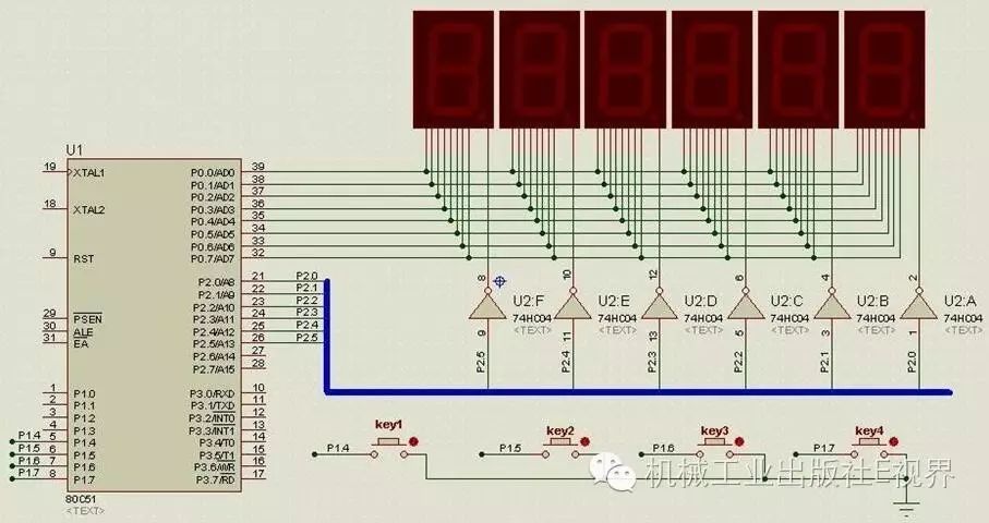 Figure1 Digital Clock Display Circuit
The digital clock program adopts a modular design. Modules can be divided according to the functional requirements of the digital clock. This process is a basic design step in the modular design of microcontroller programs. The digital clock program can be divided into display module, button module, and main program module. The button module can independently design a button subroutine, and the display module can adopt a dynamic display program, included in the timer interrupt. The main program module calls the subroutine, and the main function calls the subfunctions.
(2) Button Program
According to functional requirements, pressing key1 enters the time and alarm adjustment state. Since adjustments need to be made to different objects and the adjusted object needs to flash, a state variable to record the number of times key1 is pressed needs to be set, such as key1_flag. When key1 is not pressed, the value of key1_flag is 0, and the digital clock runs normally; the first press of key1 sets key1_flag to 1, entering the adjustment state, while the hour flashes; pressing key1 again sets key1_flag to 2, at which point the minutes flash; subsequently pressing KEY1 allows entry into other time adjustments. Since the digital clock in this project only needs to adjust 5 objects, when the value of key1_flag increases to 6, it is preset to 1, re-entering the adjustment state. The button function allocation is shown in Table 1, and the program design flow is shown in Figure 2.
Table1 Corresponding Functions of key1_flag Values
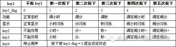
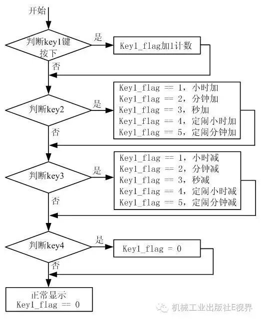 Figure2 Digital Clock Button Program Flow
Knowing the button function allocation and program flow makes it easy to design the button program. First, some global variables need to be declared, such as time variables hour (hour), min (minute), sec (second), intermediate adjustment variables hour_t, min_t, sec_t, and variables used for setting the alarm hour_r (alarm hour), min_r (alarm minute), to save the current time, adjusted time, and alarm time in program design. The button program key.c is designed as follows:
/**********************************************************/
//Button Subroutine
/**********************************************************/
#include<reg51.h>
sbit key1 = P1^4;
sbit key2 = P1^5;
sbit key3 = P1^6;
sbit key4 = P1^7;
bit key1_s,key2_s,key3_s,key4_s; //Button pressed state
unsigned char hour = 12,min = 30,sec =30; //Current time variable
char hour_t,min_t,sec_t; //Intermediate time adjustment variables
unsigned char min_r,hour_r; //Alarm time variables
unsigned char key1_flag; //Adjustment control variable, controls the adjustment and display objects
/***********************Simple Delay Function************************/
void delay(unsigned int x)
{
while(x–);
}
/*************************Button Function**************************/
void key(void)
{
//Processing for buttonkey1
if(key1== 0)
{
delay(300);
if(key1== 0);
key1_s= 1;
}
if(key1== 1 && key1_s == 1)
{
key1_s= 0;
key1_flag++;
if(key1_flag>= 6)key1_flag = 1;
hour_t= hour;//Transfer the current time to the adjusted value
min_t= min;
sec_t= sec;
}
//Processing for buttonkey2
if(key2== 0)
{
delay(300);
if(key2== 0);
key2_s= 1;
}
if(key2== 1 && key2_s == 1)
{
key2_s= 0;
if(key1_flag== 1)
hour_t++;if(hour_t>= 24)hour_t = 0;hour = hour_t; //Transfer the adjusted time to the running time
if(key1_flag== 2)min_t++;if(min_t >= 60)min_t = 0;min = min_t;
if(key1_flag== 3)sec_t++;if(sec_t >= 60)sec_t = 0;sec = sec_t;
if(key1_flag== 4)hour_r++;if(hour_r >= 24)hour = 0;
if(key1_flag== 5)min_r++;if(min_r >= 24)min_r = 0;
}
//Processing for buttonkey3
if(key3== 0)
{
delay(300);
if(key3== 0);
key3_s= 1;
}
if(key3== 1 && key3_s == 1)
{
key3_s= 0;
if(key1_flag== 1)hour_t–;if(hour_t <= 0)hour_t = 23;hour = hour_t;
if(key1_flag== 2)min_t–;if(min_t <= 0)min_t = 59;min = min_t;
if(key1_flag== 3)sec_t–;if(sec_t <= 0)sec_t = 59;sec = sec_t;
if(key1_flag== 4)hour_r–;if(hour_r <= 0)hour = 23;
if(key1_flag== 5)min_r–;if(min_r <= 0)min_r = 59;
}
//Processing for buttonkey4
if(key4 == 0)
{
delay(300);
if(key4== 0);
key4_s= 1;
}
if(key4== 1 && key4_s == 1)
{
key1_flag= 0;
key4_s= 0;
}
}
The button subroutine is stored in the key.c file for the main program to call. The modular design of the program is an advantage of microcontroller C language programming. By modularizing a complete small program unit, it can be easily called by the main program or other programs. This will be frequently used in future program designs.
(3) Main Program
The main program includes the main function, interrupt service function, and T0 initialization function, mainly completing time counting, display, and alarm handling. Since the digital clock uses a 6-digit dynamic display and utilizes the key variable key1_flag to control the display state, the program design of the digital clock can be implemented based on dynamic display.
The main function mainly calls the T0 initialization function and compares the current time with the alarm time in real-time while waiting for the T0 interrupt. The T0 interrupt service function not only needs to complete timing but also display and drive various states, such as normal state, time adjustment state, etc. The T0 interrupt service function is the key to program design and is also the difficulty of this project. Its program flow is shown in Figure 3.
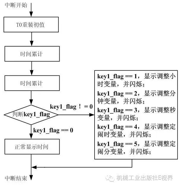 Figure 3 Digital Clock Display Program Flow
The global variable key1_flag must be declared in the main program, mainly due to the order of compilation in the program. In program design, different programs can be associated through global variables, just as global variables are used between different functions in the same program. The program of the digital clock is as follows:
/***************************************************************************/
//Digital Clock Main Program, with Time Adjustment and Alarm Functionality
/***************************************************************************/
#include<reg51.h>
#include<key.c>
unsigned char i,j,k;
unsigned char seven_seg[] ={0xc0,0xf9,0xa4,0xb0,0x99,0x92,0x82,0xf8,0x80,0x90};
unsigned char flash;
sbit SW = P3^3; //Connects to relay driver circuit, low level relay engages, controls the bell
/***************************************************************************/
void timer0_isr(void) interrupt 1
{
TH0 =0xf8;
TL0 = 0x2f;
i++;
if(i>= 250) //Half a second elapsed
{
flash= ~flash;// Get the 8-bit flashing variable
i= 0;
j++;
}
if(j>= 2) //1Minute elapsed
{
sec++;
j= 0;
}
if(sec>= 60) //1Minute elapsed
{
min++;
sec= 0;
}
if(min>= 60) //1Hour elapsed
{
hour++;
min= 0;
}
if(hour>= 24)
hour = 0;
P0= 0xff;//Simulation blanking
if(key1_flag== 0)//Normal timing
{
switch(k)
{
case0:P0 = seven_seg[sec % 10]; P2 = ~0x01;break;
case1:P0 = seven_seg[sec / 10]; P2 = ~0x02;break;
case2:P0 = seven_seg[min % 10] & (0x7f| flash); P2 = ~0x04;break;//Decimal point flashes
case3:P0 = seven_seg[min / 10]; P2 = ~0x08;break;
case4:P0 = seven_seg[hour % 10] & (0x7f| flash); P2 = ~0x10;break; //Decimal point flashes
case5:P0 = seven_seg[hour / 10]; P2 = ~0x20;break;
}
}
if(key1_flag== 1)//Adjust hour, hour flashes
{
j= 0;
switch(k)
{
case0: P0 = seven_seg[sec_t % 10]; P2 = ~0x01;break;
case1: P0 = seven_seg[sec_t / 10]; P2 = ~0x02;break;
case2: P0 = seven_seg[min_t % 10]; P2 = ~0x04;break;
case3: P0 = seven_seg[min_t / 10]; P2 = ~0x08;break;
case4: P0 = seven_seg[hour_t % 10] | flash; P2 = ~0x10;break; //Hour flashes
case5: P0 = seven_seg[hour_t / 10] | flash; P2 = ~0x20;break; //Hour flashes
}
}
if(key1_flag== 2)//Adjust minutes
{
j= 0;
switch(k)
{
case0: P0 = seven_seg[sec_t % 10]; P2 = ~0x01;break;
case1: P0 = seven_seg[sec_t / 10]; P2 = ~0x02;break;
case2: P0 = seven_seg[min_t % 10]| flash; P2 = ~0x04;break; //Minutes flash
case3: P0 = seven_seg[min_t / 10]| flash; P2 = ~0x08;break; //Minutes flash
case4: P0 = seven_seg[hour_t % 10] ; P2 = ~0x10;break;
case5: P0 = seven_seg[hour_t / 10]; P2 = ~0x20;break;
}
}
if(key1_flag== 3)//Adjust seconds
{
j= 0;
switch(k)
{
case0: P0 = seven_seg[sec_t % 10]| flash; P2 = ~0x01;break; //Seconds flash
case1: P0 = seven_seg[sec_t / 10]| flash; P2 = ~0x02;break; //Seconds flash
case2: P0 = seven_seg[min_t % 10]; P2 = ~0x04;break;
case3: P0 = seven_seg[min_t / 10]; P2 = ~0x08;break;
case4: P0 = seven_seg[hour_t % 10] ; P2 = ~0x10;break;
case5: P0 = seven_seg[hour_t / 10]; P2 = ~0x20;break;
}
}
if(key1_flag== 4)//Adjust alarm hour
{
j= 0;
switch(k)
{
case0: P0 = seven_seg[min_r % 10]; P2 = ~0x01;break;
case1: P0 = seven_seg[min_r / 10]; P2 = ~0x02;break;
case2: P0 = seven_seg[hour_r % 10]| flash; P2 = ~0x04;break; //Alarm hour flashes
case3: P0 = seven_seg[hour_r / 10]| flash;P2 = ~0x08;break; //Alarm hour flashes
case4: P0 = 0xff;P2 = ~0x10;break;//No display
case5: P0 = 0x0c;P2 =~0x20;break;//Display character“P”
}
}
if(key1_flag== 5) //Adjust alarm minutes
{
j= 0;
switch(k)
{
case0: P0 = seven_seg[min_r % 10]| flash; P2 = ~0x01;break; //Alarm minutes flash
case1: P0 = seven_seg[min_r / 10]| flash; P2 = ~0x02;break; //Alarm minutes flash
case2: P0 = seven_seg[hour_r % 10]; P2 = ~0x04;break;
case3: P0 = seven_seg[hour_r / 10]; P2 =~0x08;break;
case4: P0 = 0xff;P2 = ~0x10;break;//No display
case5: P0 = 0x0c;P2 =~0x20;break;//Display character“P”
}
}
k++;
if(k>= 6)k = 0;
}
/***************************************************************************/
void timer0_initi(void)
{
TMOD =0x01;
TH0 =0xf8;
TL0 = 0x2f;
EA = 1;
ET0 = 1;
TR0 = 1;
}
/***************************************************************************/
void main(void)
{
timer0_initi();
while(1)
{
key();
if(min== min_r && hour == hour_r)
SW= 0;
else
SW= 1;
}
}
After completing the design of the button subroutine and the main program, save them in the same directory. When designing the program using Keil, directly add the main program after creating the new project. Since there are many similar structures and programs in the program, when writing the digital clock program, the copy and paste function should be used as much as possible, changing only different variable values, thus greatly reducing the program input volume.
This project focuses on practicing basic skills in microcontroller program design. Once everyone is familiar with the project tasks, as long as the button function allocation is reasonable and the writing ideas are clear, the design of the digital clock can be completed in a very short time. Implementing the design of a digital clock using a microcontroller is the most typical training project in microcontroller program design. Therefore, having the ability to independently complete the design of a digital clock is the minimum requirement for microcontroller project development and product design.
Selected from “Microcontroller Development from Beginner to Proficiency” by Bai Linfeng et al.
Previous Highlights
Classic for beginners in microcontrollers! 25 project materials are freely distributed!
Making a high-frequency transformer