Product Structure Design Course: Bluetooth Speaker Teaching Section: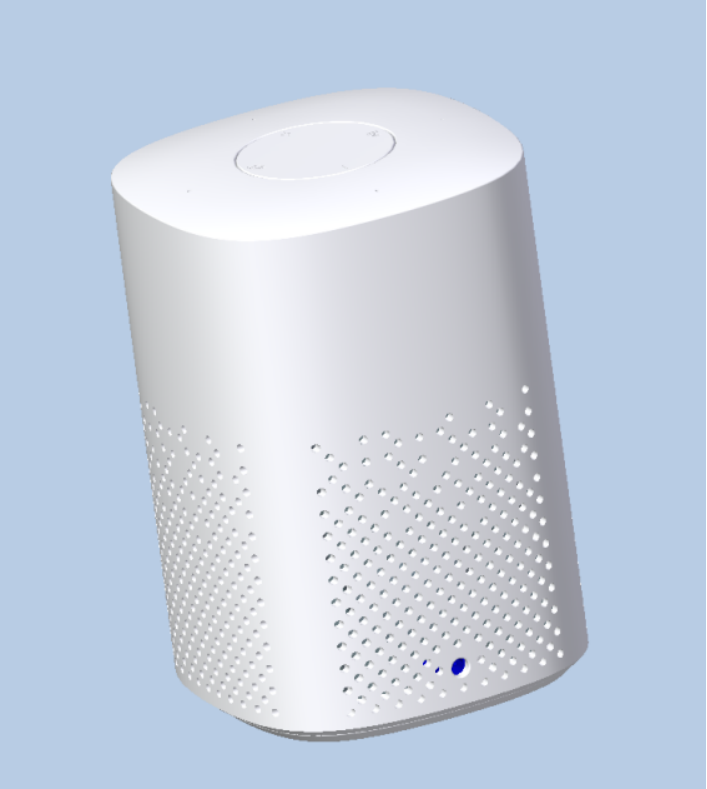
Modeling Analysis
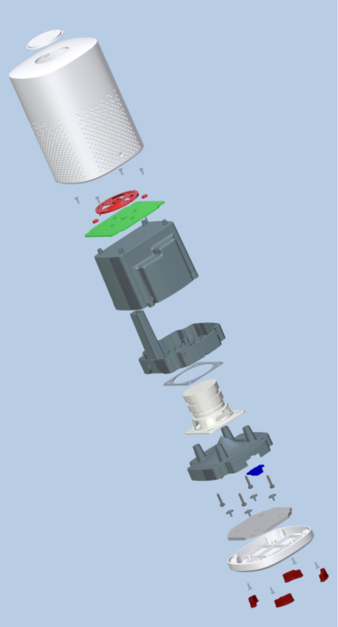
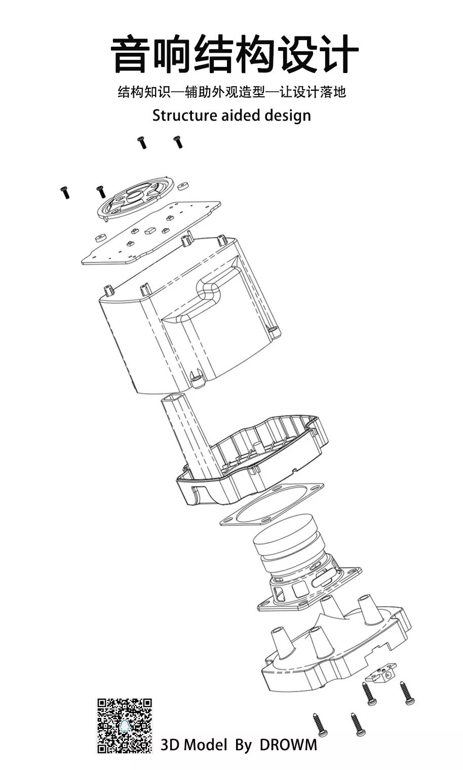
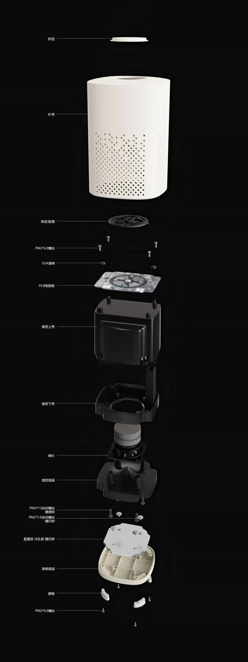
First, the appearance design needs to be completed by an industrial designer using modeling software, and then the structural engineer improves the internal structure based on the functional requirements of the appearance. Looking at the rendered image of the finished product, we find that the shell mainly consists of an upper and lower shell, volume buttons, power socket, and foot pads. Each shell component needs to be modeled individually, and the internal structure must be refined according to functionality. Based on the industrial designer’s requirements, we can conclude that the product assembly method is to assemble from top to bottom.The speaker has buttons and Bluetooth connection control, so the PCB must be designed below the buttons. Inside, a speaker must be placed to provide sound source, and to control sound quality, the speaker must have an internal acoustic chamber structure. Generally, large companies will have acoustic structural engineers who provide structural solutions for speaker products.
Modeling Steps
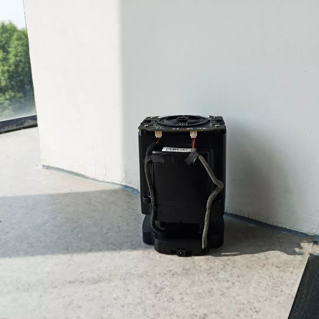
(1) The course will guide students through the disassembly of the model, step by step learning about assembly knowledge, material usage, and processing techniques, understanding the feasibility and practicality of the structure, and how to facilitate product use, as well as understanding the mold separation features to control production costs effectively.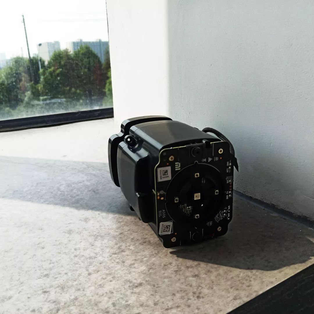
 (2) Since most students have taken advanced Rhino courses, they will use Rhino software to complete the shell design, while the structural interface only needs to complete the appearance; details and engineering chamfers do not need to be done to facilitate subsequent structural development. The modeling quality in Rhino must be high, with the simplest surfaces and no broken or excessive small surfaces (those who are not familiar with Rhino can directly use CREO/Proe to draw the speaker shell, which is more convenient for later structural modifications of the appearance).
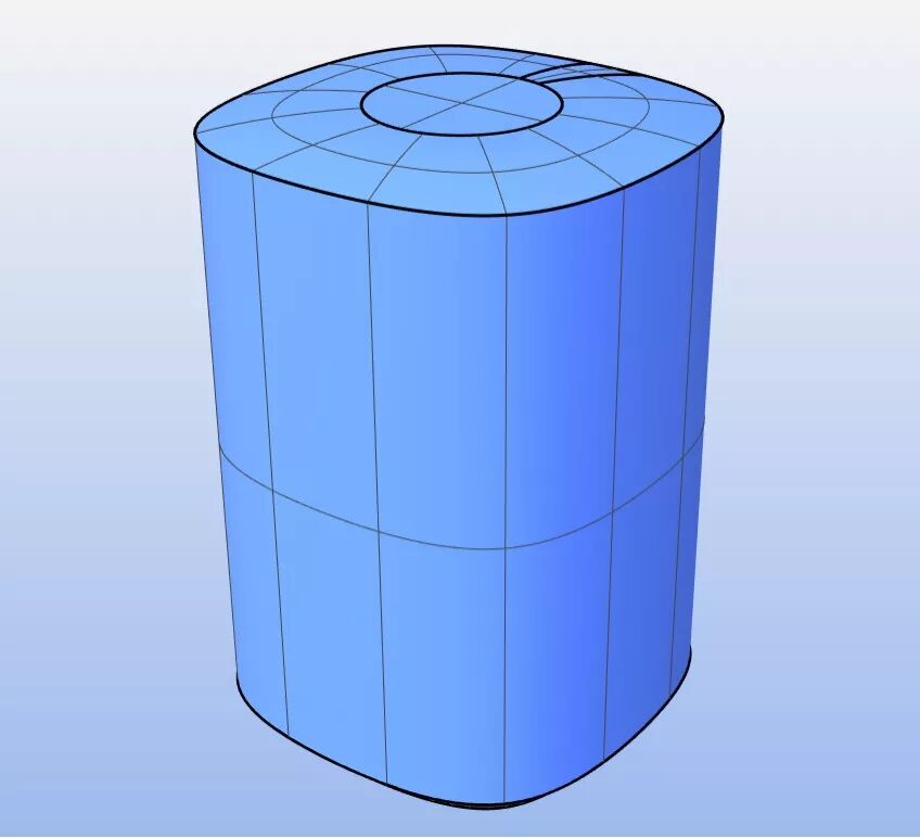 (3) Import the Creo/Proe model to represent the Rhino modeling surface as a solid feature. If the product model built in Rhino is not the simplest surface, then PROE will show that the surface is not smooth enough.
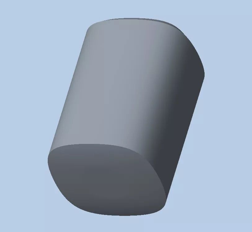 (4) Use the imported speaker model to split the upper shell in the 003 diagram. This speaker has many small holes around it for sound dispersion, so its shell does not need to have draft angles. During mold opening, four sides need to have runners for the sound dispersion holes. However, since the internal mold opens from top to bottom, the internal shell needs to have draft angles, and the sound dispersion holes should be refined according to the rendered image.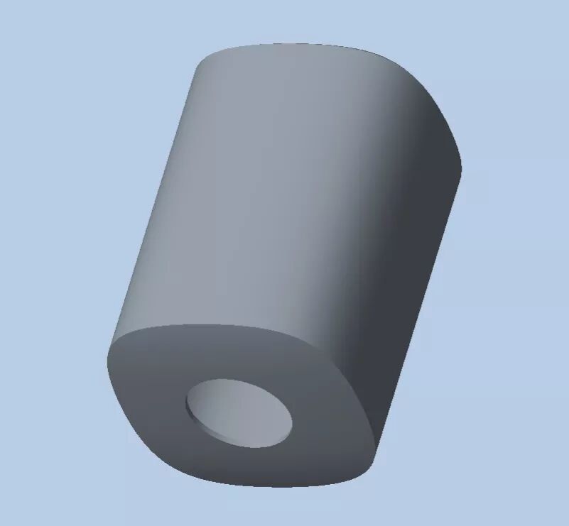
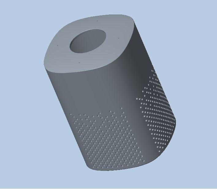 (5) Use the imported speaker model to split the base in the 005 diagram, paying attention to the draft angles. After splitting the shell, first reserve the assembly position for the foot pads.
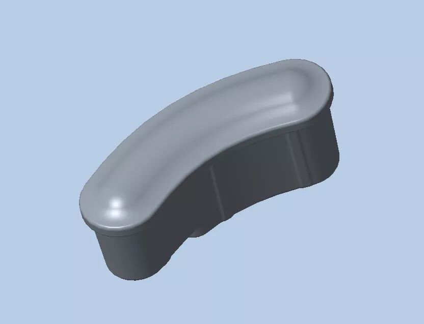
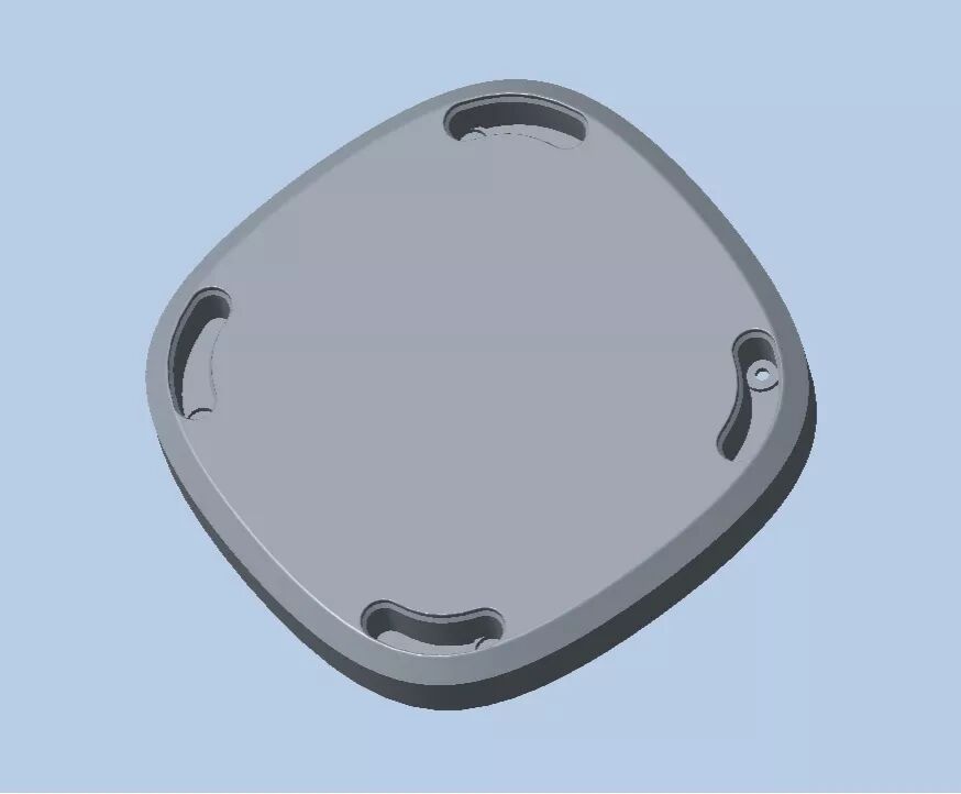 (6) The bottom of the speaker has four soft foot pads, so the foot pads should also be separated. Structurally, the foot pads are an interference fit. The foot pad model can be created by copying the geometry of the base foot pad holes.
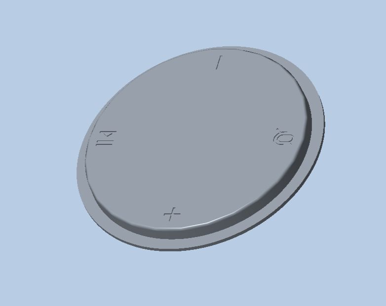
 (7) Use the imported speaker model to split out the buttons and label the button symbols.
 (8) Assemble the split upper shell, base, foot pads, and buttons in the assembly module.
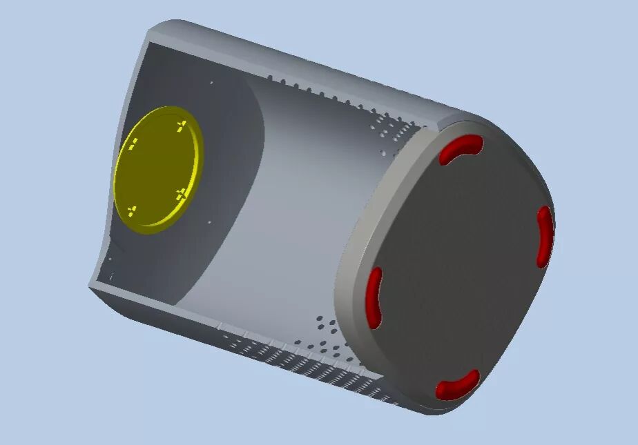 (9) Design the PCB circuit control board based on the internal space of the shell. Set standard component surface mount buttons below the button icons, and set the spacing for the buttons to be assembled into the assembly diagram.
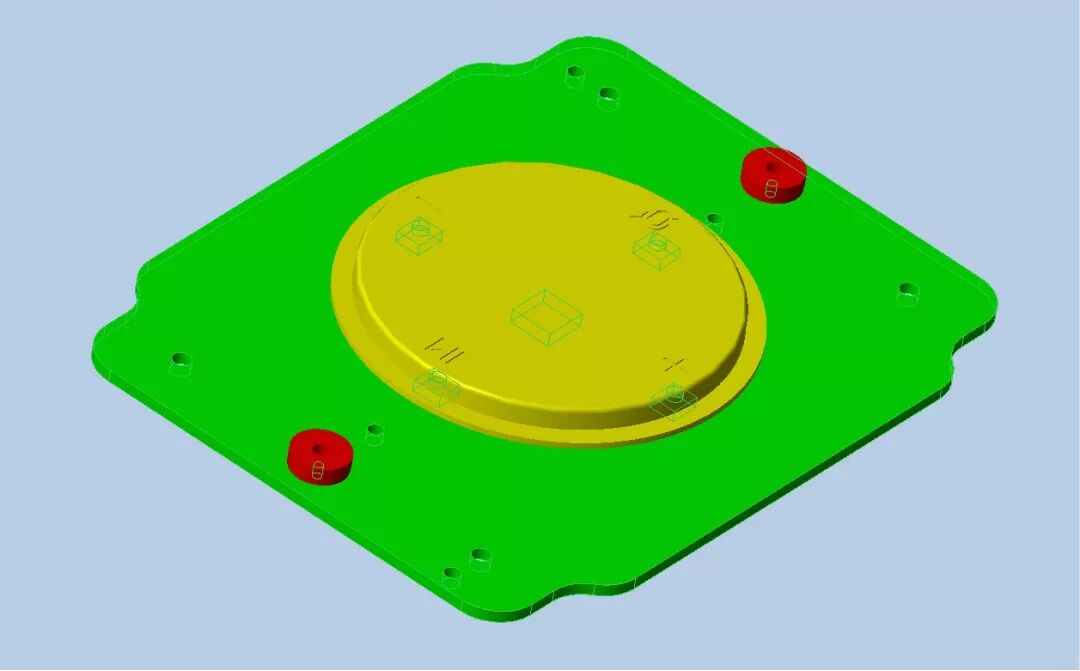 (10) Since the buttons are made of plastic, direct contact with the buttons will affect the feel, so we need to add a soft rubber support pad between the two for a transitional effect.
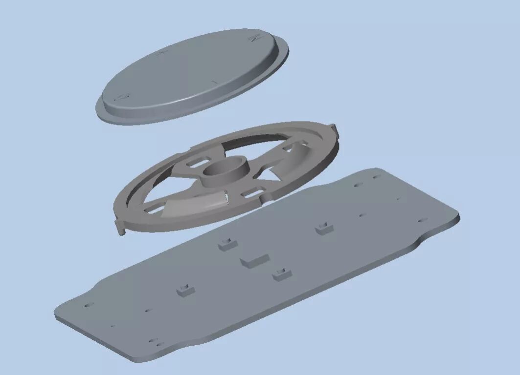 (11) After assembling the PCB board, it needs to be designed with positioning limits to increase rib positions.
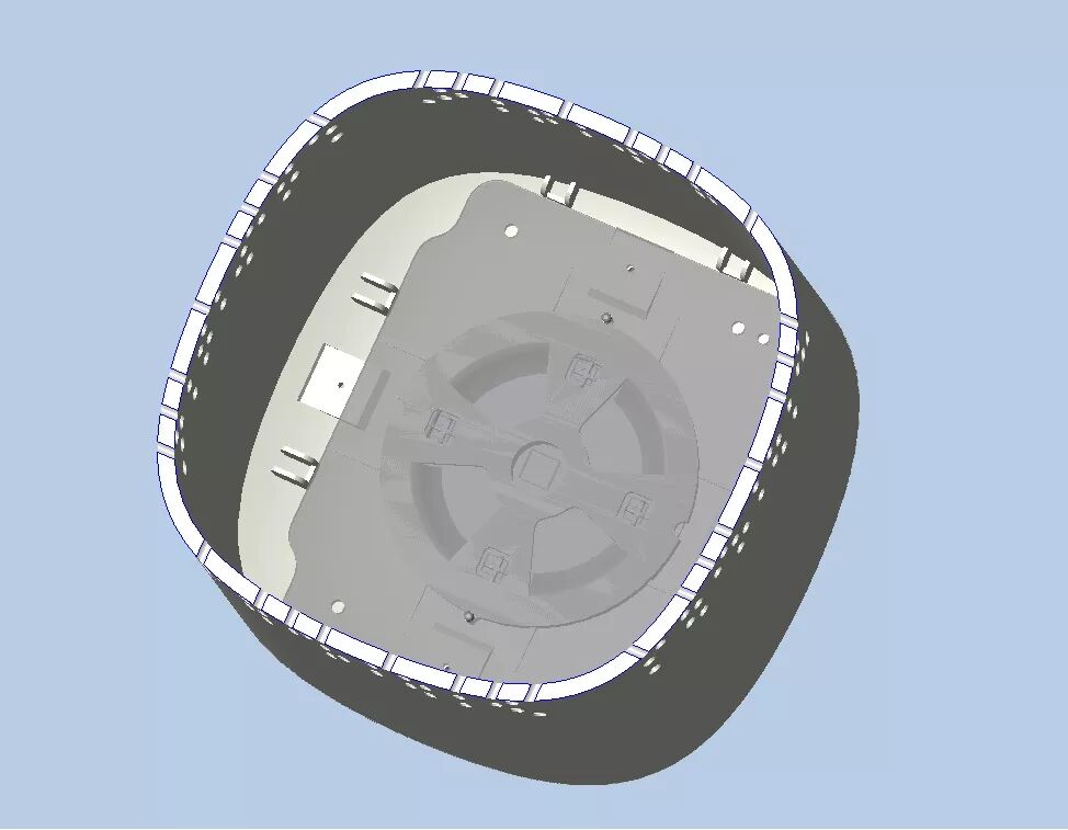 (12) Design the acoustic chamber space based on the internal space of the shell combined with acoustic knowledge. The chamber needs to be sealed, so the upper and lower shells can be ultrasonically fused together. This enhances the overall sealing and prepares for producing excellent sound quality.
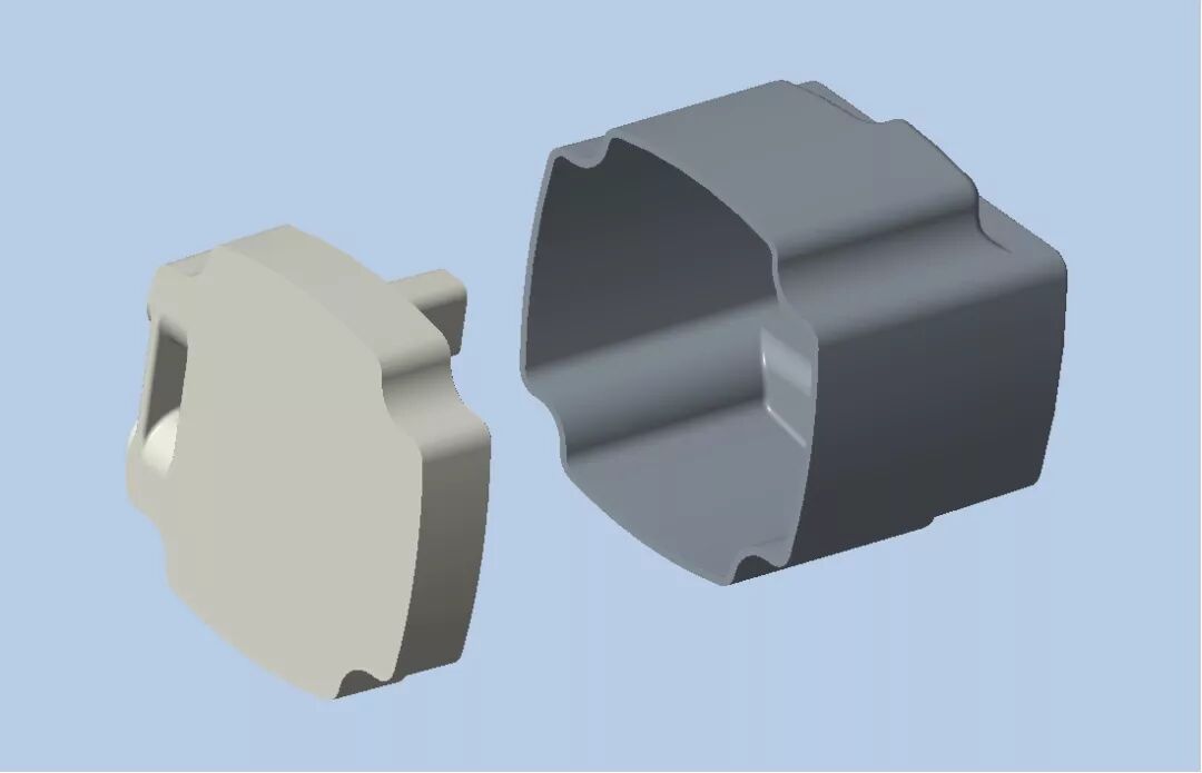 (13) Ultrasonic fusion requires withstanding certain pressure to prevent shell deformation, so the shell needs to be reinforced with ribs. Also, consider how the chamber connects and assembles with the outer shell, designing four openings to connect with the inner wall of the outer shell.
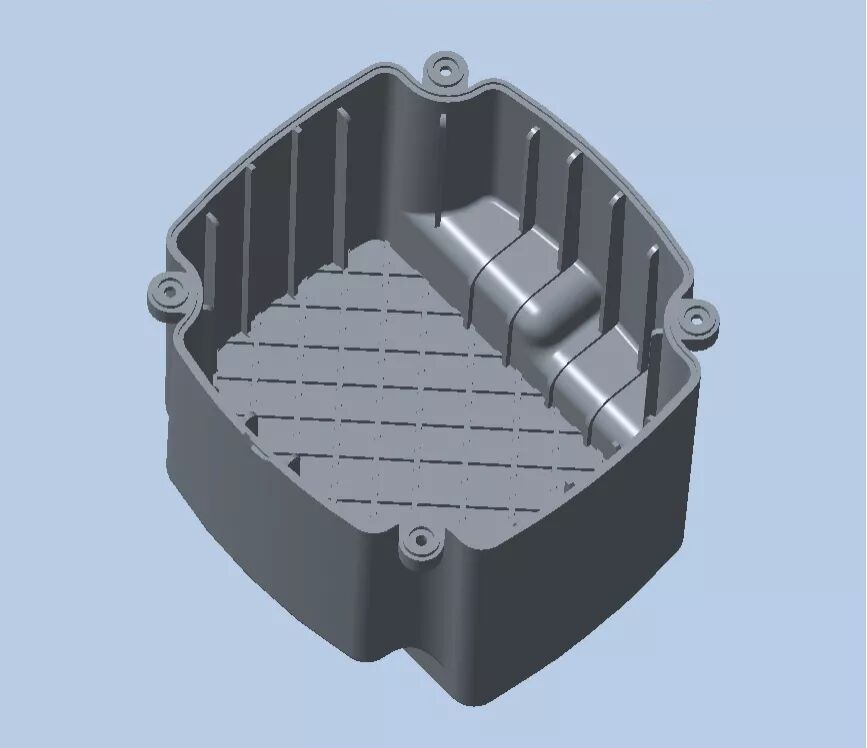 (14) After selecting the speaker, assemble the speaker model into the chamber. It can be designed to be fixed to the lower shell of the chamber using screws, and design positioning and rib positions in the assembly diagram.
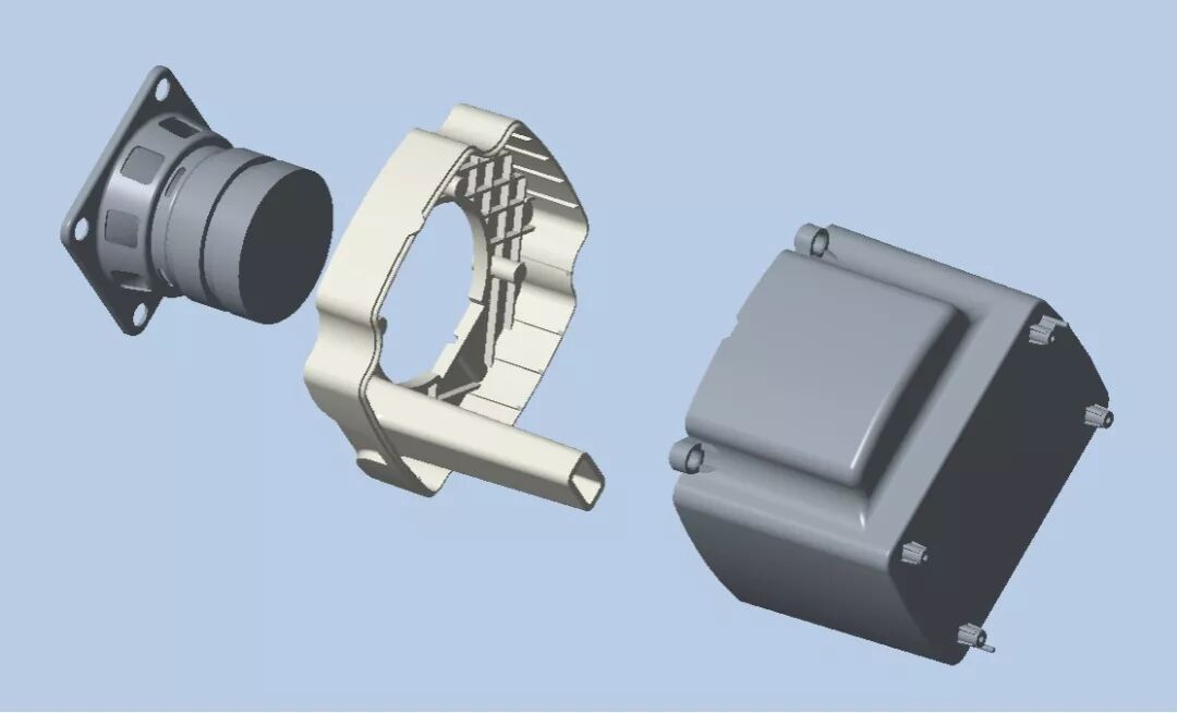 (15) Create a conical arc shell for the speaker’s sound outlet to evenly disperse sound through the round holes in the outer shell.
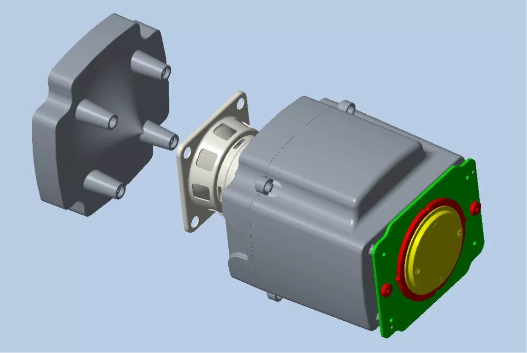 (16) Fix the acoustic chamber structure inside the outer shell. Secure it using screws, adding locking positions and reinforcing ribs in the shell.
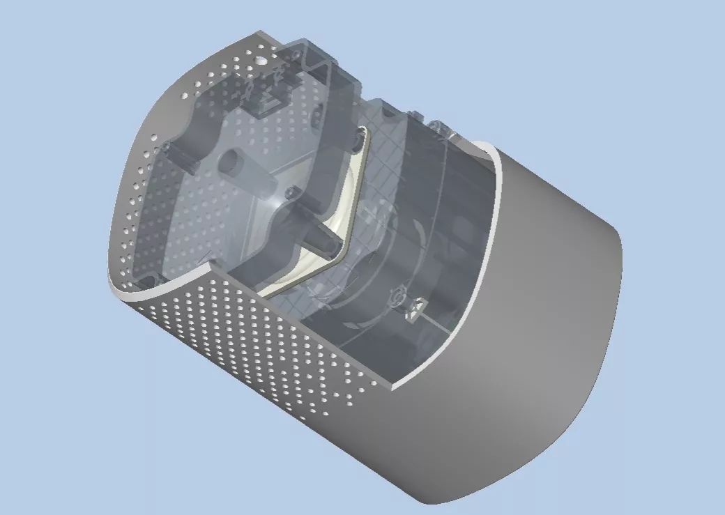 (17) Design fixed positioning for the power interface standard components.
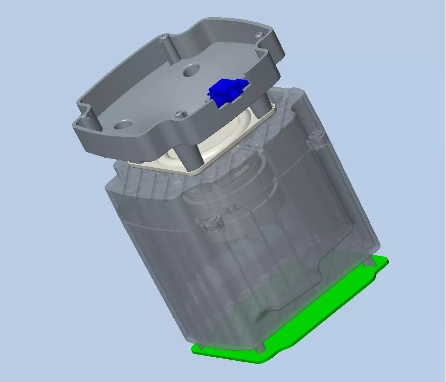 (18) Since the speaker stands on the table, add a weight pad at the bottom to increase its stability. The red weight block in the image can be made of cold-rolled plate material, galvanized, and fixed at the bottom.
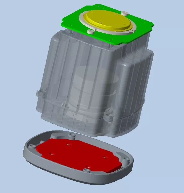 (19) In CAD, generate engineering assembly views to detail each part’s materials, surface treatments, and processing techniques.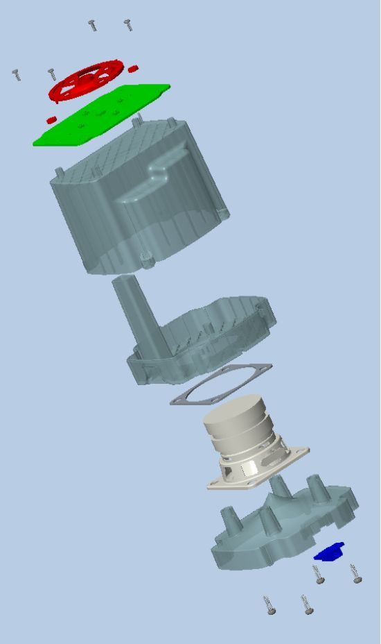
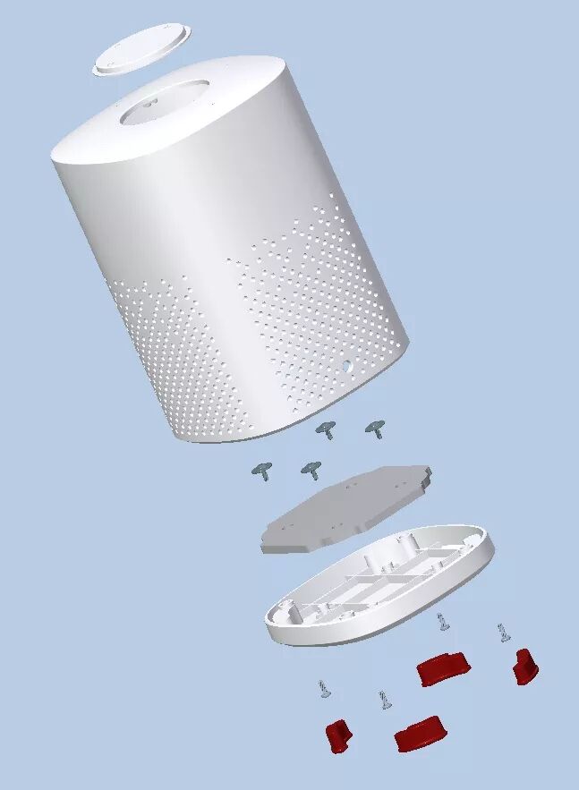
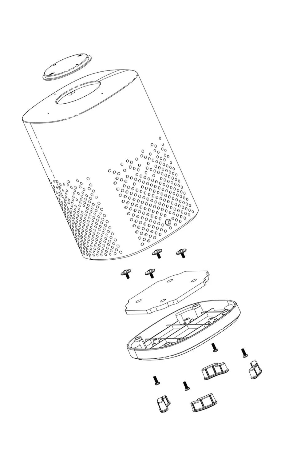 (21) Final rendered annotation diagram.
 This concludes our structural design assistance for the speaker. Did everyone learn something?In fact, learning requires a lot of practice to become proficient.Many friends may have seen many tutorials on the website but are still unfamiliar with the software menu functions.Trust me, once you start practicing, as long as you follow each tutorial carefully and practice repeatedly, you will definitely achieve results.