 Project Baidu Cloud Source Code Path:
https://pan.baidu.com/s/1SG5pf87MnbFOuAzbI5kxDQ?pwd=cjz7
1. Hardware Platform Introduction
The hardware platform MCU uses the ESP32-S3 module with 8MB PSRAM and 16MB FLASH;
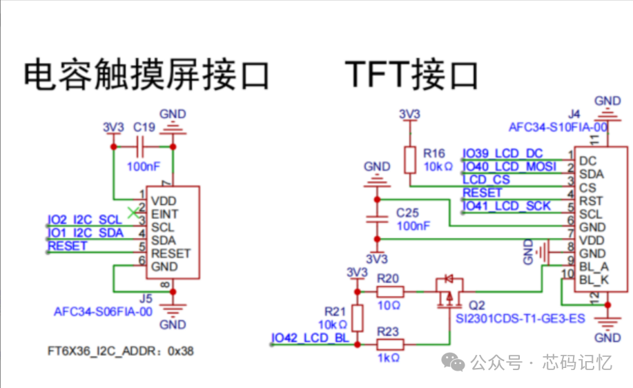
The LCD screen is a 2.0-inch IPS high-definition LCD with a resolution of 240*320; the LCD driver chip is ST7789, connected via SPI to the ESP32-S3;
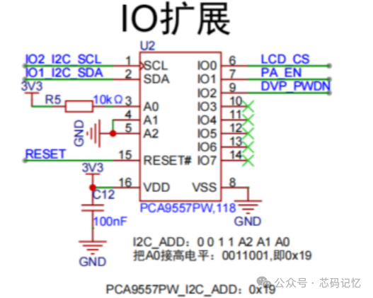
The LCD_CS pin of the LCD screen is controlled by the IO expansion chip PCA9557, which communicates with the MCU via I2C.
The touchscreen chip used is FT6336, which communicates with the ESP32-S3 via I2C;
The schematic diagram is shown below:
2. Software Engineering Setup
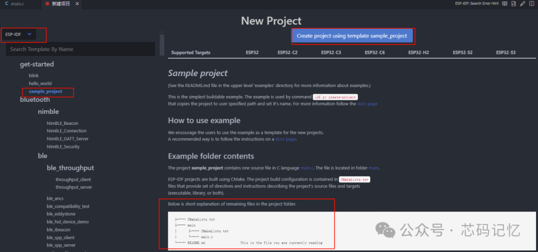
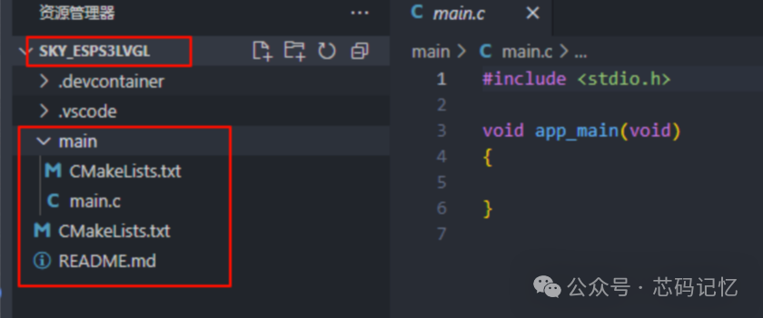
2.1. Create a Basic Project
First, create a new project based on the simplest project sample_project in the ESP-IDF v5.1.5 environment, as shown in the figure below:
2.2. Writing PCA9557 Driver
The driver file for PCA9557, pca9577.c, is as follows:
#include "pca9557.h"
/** * @brief bsp_i2c_init *  * @return esp_err_t  */esp_err_t bsp_i2c_init(void){    i2c_config_t i2c_conf  = {        .mode = I2C_MODE_MASTER,        .sda_io_num = BSP_I2C_SDA,        .sda_pullup_en = GPIO_PULLUP_ENABLE,        .scl_io_num = BSP_I2C_SCL,        .scl_pullup_en = GPIO_PULLUP_ENABLE,        .master.clk_speed = BSP_I2C_FREQ_HZ    };    i2c_param_config(BSP_I2C_NUM, &i2c_conf);
    return i2c_driver_install(BSP_I2C_NUM, i2c_conf.mode, 0, 0, 0);}
/** * @brief Read the value of PCA9557 register *  * @param reg_addr  * @param data  * @param len  * @return esp_err_t  */esp_err_t pca9557_register_read(uint8_t reg_addr, uint8_t *data, uint32_t len){    return i2c_master_write_read_device(BSP_I2C_NUM, PCA9557_SENSOR_ADDR, &reg_addr, 1, data, len, 1000 / portTICK_PERIOD_MS );}
/** * @brief Write value to PCA9557 register *  * @param reg_addr  * @param data  * @return esp_err_t  */esp_err_t pca9557_register_write_byte(uint8_t reg_addr, uint8_t data){    uint8_t data_buf[2] = {reg_addr, data};    return i2c_master_write_to_device(BSP_I2C_NUM, PCA9557_SENSOR_ADDR, data_buf, sizeof(data_buf), 1000 / portTICK_PERIOD_MS);}
/** * @brief Initialize PCA9557 IO expansion chip * @param NULL */void pca9557_init(void){    // Write default values to control pins DVP_PWDN =1 PA_EN = 0 LCD_CS = 1    pca9557_register_write_byte(PCA9577_OUTPUT_PORT, 0x05);    // Set PCA9557 chip IO0 IO1 IO2 as output, other pins remain default input    pca9557_register_write_byte(PCA9557_CONFIGURATION_PORT, 0xf8);}
/** * @brief Set a certain IO pin of PCA9557 chip to high or low level *  * @param gpio_bit  * @param level High or low level * @return esp_err_t  */esp_err_t pca9557_set_output_state(uint8_t gpio_bit, uint8_t level){    uint8_t data;    esp_err_t res = ESP_FAIL;    pca9557_register_read(PCA9577_OUTPUT_PORT, &data, 1);    res = pca9557_register_write_byte(PCA9577_OUTPUT_PORT, SET_BITS(data, gpio_bit, level));
    return res;}
/** * @brief Control PCA8557_LCD_CS pin output high or low level *  * @param level 0: output low level 1: output high level */void lcd_cs(uint8_t level){    pca9557_set_output_state(LCD_CS_GPIO, level);}

#if 0/** * @brief Control PCA8557_PA_EN pin output high or low level *  * @param level 0: output low level 1: output high level */void pa_en(uint8_t level){    pca9557_set_output_state(PA_EN_GPIO, level);}
/** * @brief Control PCA8557_DVP_PWDN pin output high or low level *  * @param level 0: output low level 1: output high level */void dvp_pwdn(uint8_t level){    pca9557_set_output_state(DVP_PWDN_GPIO, level);}#endif
The content of the pca9577.h file is as follows:
#ifndef __PCA9557_H__
#define __PCA9557_H__
#include "driver/gpio.h"
#include "driver/i2c.h"
#include "esp_err.h"
#include "freertos/FreeRTOS.h"
#include "freertos/portmacro.h"
/********************************************************************* *************************** I2C Configuration **********************************//* Pin and related parameter definitions */#define BSP_I2C_SDA           (GPIO_NUM_1)   // SDA pin#define BSP_I2C_SCL           (GPIO_NUM_2)   // SCL pin
#define BSP_I2C_NUM           (0)            // I2C peripheral num#define BSP_I2C_FREQ_HZ       100000         // Rate 100kHz
/********************************************************************* * ************************** IO Expansion Chip ******************************/#define PCA9557_INPUT_PORT              0x00#define PCA9577_OUTPUT_PORT             0x01#define PCA9577_POLARITY_INVERSION_PORT 0x02#define PCA9557_CONFIGURATION_PORT      0x03
#define LCD_CS_GPIO                     BIT(0)              //PCA9557_GPIO_NUM_1#define PA_EN_GPIO                      BIT(1)              //PCA9557_GPIO_NUM_2#define DVP_PWDN_GPIO                   BIT(2)              //PCA9557_GPIO_NUM_3
#define PCA9557_SENSOR_ADDR             0x19                /*Slave address of the PCA9557 sensor*/#define SET_BITS(_m, _s, _v)  ((_v) ? (_m)|((_s)) : (_m)&~((_s)))
extern esp_err_t bsp_i2c_init(void);
extern void pca9557_init(void);
extern void lcd_cs(uint8_t level);// extern void pa_en(uint8_t level);// extern void dvp_pwdn(uint8_t level);
#endif
2.3. Writing FT6336 Driver
The touchscreen controller model is F6336, and the driver for this chip does not need to be written by yourself; you can directly use the Espressif component esp_lcd_touch_ft5x06. The initialization code for the touchscreen is as follows:
/** * @brief bsp_touch_new * @note Touchscreen initialization * @param ret_touch  * @return esp_err_t  */esp_err_t bsp_touch_new(esp_lcd_touch_handle_t *ret_touch){    /* Initialize touch */    esp_lcd_touch_config_t tp_cfg = {        .x_max = BSP_LCD_W_PIX,        .y_max = BSP_LCD_H_PIX,        .rst_gpio_num = GPIO_NUM_NC, // Shared with LCD reset        .int_gpio_num = GPIO_NUM_NC,         .levels = {            .reset = 0,            .interrupt = 0,        },        .flags = {            .swap_xy = 0,            .mirror_x = 1,            .mirror_y = 0,        },    };    esp_lcd_panel_io_handle_t tp_io_handle = NULL;    esp_lcd_panel_io_i2c_config_t tp_io_config = ESP_LCD_TOUCH_IO_I2C_FT5x06_CONFIG();
    ESP_RETURN_ON_ERROR(esp_lcd_new_panel_io_i2c((esp_lcd_i2c_bus_handle_t)BSP_I2C_NUM, &tp_io_config, &tp_io_handle), TAG, "");    ESP_ERROR_CHECK(esp_lcd_touch_new_i2c_ft5x06(tp_io_handle, &tp_cfg, ret_touch));
    return ESP_OK;}
2.4. Writing LCD Driver
The initialization code for the LCD display is as follows:bsp_lcd_init API interface function:
/** * @brief LCD display initialization *  * @return esp_err_t  */esp_err_t bsp_lcd_init(void){    esp_err_t ret = ESP_OK;
    ret = bsp_display_init();                                   // LCD driver initialization    bsp_touch_new(&tp);                                         // Touchscreen initialization    lcd_set_color(0x669E);                                      // Set the entire screen background to black    ret = esp_lcd_panel_disp_on_off(panel_handle, true);        // Turn on the LCD display    ret = bsp_display_backlight_on();                           // Turn on the backlight display
    return ret;}
The LCD driver chip used is the ST7789 chip, and the driver initialization API interfacebsp_display_init()is as follows:
esp_err_t bsp_display_init(void){    esp_err_t ret = ESP_OK;    // Backlight initialization    ESP_RETURN_ON_ERROR(bsp_display_brightness_init(), TAG, "Brightness init failed");
    ESP_LOGI(TAG, "Initialize SPI bus");    const spi_bus_config_t spi_conf = {        .sclk_io_num = BSP_LCD_SPI_CLK_PIN,        .mosi_io_num = BSP_LCD_SPI_MOSI_PIN,        .miso_io_num = GPIO_NUM_NC,        .quadwp_io_num = GPIO_NUM_NC,        .quadhd_io_num = GPIO_NUM_NC,        .max_transfer_sz = BSP_LCD_H_PIX * BSP_LCD_W_PIX * sizeof(uint16_t),        };    ESP_RETURN_ON_ERROR(spi_bus_initialize(BSP_LCD_SPI_NUM, &spi_conf, SPI_DMA_CH_AUTO), TAG, "SPI init failed");    // LCD control IO initialization    ESP_LOGI(TAG, "Install panel IO");    const esp_lcd_panel_io_spi_config_t io_conf = {        .dc_gpio_num = BSP_LCD_DC_PIN,        .cs_gpio_num = BSP_LCD_SPI_CS_PIN,        .pclk_hz = BSP_LCD_PIXEL_CLOCK_HZ,        .lcd_cmd_bits = LCD_CMD_BITS,        .lcd_param_bits = LCD_PARAM_BITS,        .spi_mode = 2,         .trans_queue_depth = 10,    };    ESP_GOTO_ON_ERROR(esp_lcd_new_panel_io_spi((esp_lcd_spi_bus_handle_t)BSP_LCD_SPI_NUM, &io_conf, &io_handle), err, TAG, "New panel IO failed");
    // Initialize the LCD driver chip ST7789    ESP_LOGI(TAG, "Install LCD driver");    const esp_lcd_panel_dev_config_t panel_config = {        .reset_gpio_num = BSP_LCD_RST_PIN,        .rgb_ele_order = LCD_RGB_ELEMENT_ORDER_RGB,        .bits_per_pixel = BSP_LCD_BITS_PER_PIXEL,    };    ESP_GOTO_ON_ERROR(esp_lcd_new_panel_st7789(io_handle, &panel_config, &panel_handle), err, TAG, "NEW panel failed");
    esp_lcd_panel_reset(panel_handle);                      // Reset the LCD screen    lcd_cs(0);                                              // Pull down CS pin    esp_lcd_panel_init(panel_handle);                       // Initialize configuration registers    esp_lcd_panel_invert_color(panel_handle, true);         // Color inversion    esp_lcd_panel_swap_xy(panel_handle, true);              // Display inversion    esp_lcd_panel_mirror(panel_handle, true, false);        // Mirroring
    return ret;
err:    if(panel_handle){        esp_lcd_panel_del(panel_handle);    }    if(io_handle){        esp_lcd_panel_io_del(io_handle);    }    spi_bus_free(BSP_LCD_SPI_NUM);    return ret;}
The PWM initialization API interface for the LCD backlight is as follows:bsp_display_brightness_init()is as follows:
/** * @brief bsp_display_brightness_init * @param NULL * @return esp_err_t * @note Backlight PWM initialization */esp_err_t bsp_display_brightness_init(void){ const ledc_channel_config_t LCD_backlight_channel = { .gpio_num = BSP_LCD_BACKLIGHT_PIN, .speed_mode = LEDC_LOW_SPEED_MODE, .channel = LCD_LEDC_CH, .intr_type = LEDC_INTR_DISABLE, // Disable interrupt .timer_sel = 1, .duty = 0, .hpoint = 0, .flags.output_invert = true }; const ledc_timer_config_t LCD_backlight_timer = { .speed_mode = LEDC_LOW_SPEED_MODE, .duty_resolution = LEDC_TIMER_10_BIT, .timer_num = 1, .freq_hz = 5000, .clk_cfg = LEDC_AUTO_CLK };
ESP_ERROR_CHECK(ledc_timer_config(&LCD_backlight_timer)); ESP_ERROR_CHECK(ledc_channel_config(&LCD_backlight_channel));
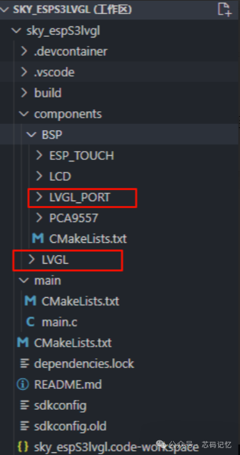
return ESP_OK;}3. Porting LVGL
Espressif provides the lvgl and esp_lvgl_port components, which we can directly download and add to the components directory of our project, as shown in the figure below:
The LVGL initialization code is as follows:
// Development board display initializationvoid bsp_lvgl_start(void){    /* Initialize LVGL */    lvgl_port_cfg_t lvgl_cfg = ESP_LVGL_PORT_INIT_CONFIG();    lvgl_port_init(&lvgl_cfg);
    /* Initialize LCD and add LVGL interface */    disp = bsp_display_lcd_init();
    /* Initialize touchscreen and add LVGL interface */    disp_indev = bsp_display_indev_init(disp);
    /* Turn on the LCD backlight */    bsp_display_backlight_on();
}
Then call the following function in the app_main function:
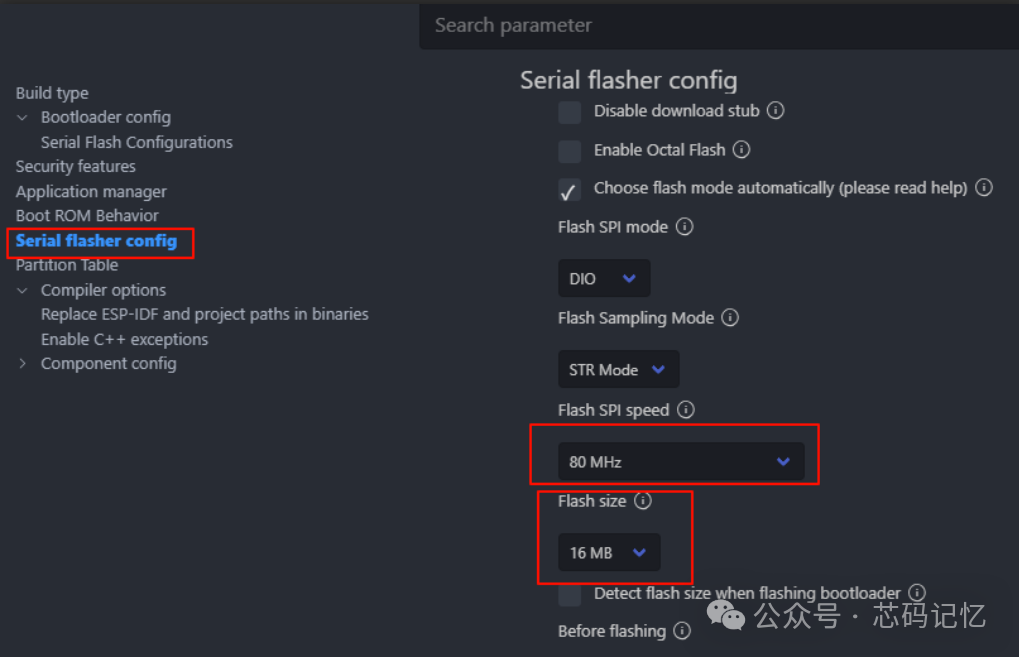
void app_main(void){ bsp_i2c_init(); // I2C initialization pca9557_init(); // IO expansion chip initialization bsp_lvgl_start(); // Initialize LVGL lv_demo_music(); // Call LVGL music demo}Finally, select the target chip ESP32S3 and configure menuconfig, as shown in the figure below:

1. Configure the flash size to 16MB, as shown in the figure below:
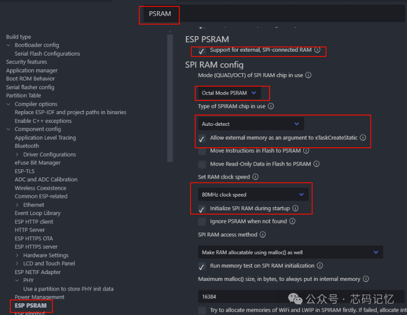
2. Configure to support PSRAM, as shown in the figure below:
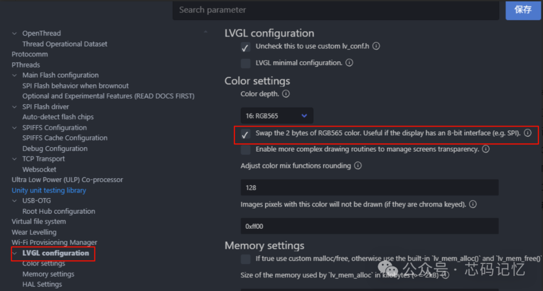
3. Configuration of LVGL components for color, demo, and font
The color of LVGL needs to be set to inverted, as shown in the figure below:
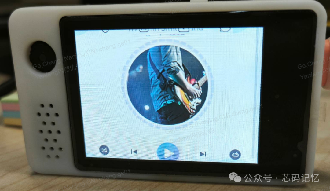
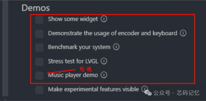
Select the LVGL demo to use; the official LVGL provides 5 demos, here we choose the music player demo, as shown in the figure below:
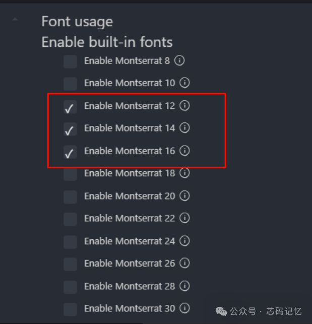
The music player demo requires the use of LVGL’s 12-pixel and 16-pixel font sizes, and the font settings are as follows:
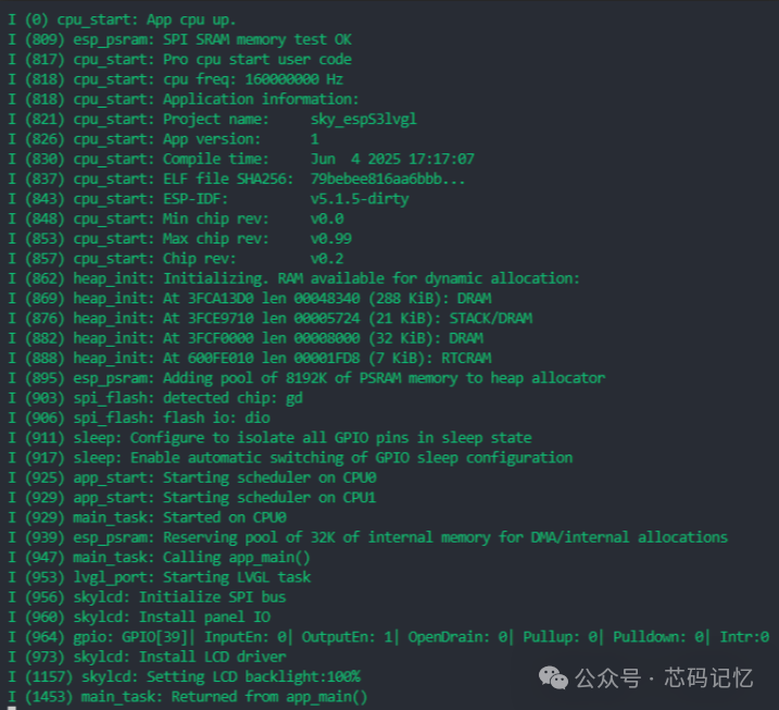
After clicking save, close it. The porting work is complete; compile the program and download it to see the effect; the device port prints logs as follows: