Introduction
PID control (Proportional-Integral-Derivative control) has a wide range of applications in industrial control and robotic control. This article takes robotic arm joint control as an example to explore the implementation and optimization of PID control in ROS. Unlike vision-related applications, this article focuses on the servo control of robotic arms, discussing how to adjust the position or speed of joint motors through PID to ensure they quickly and smoothly reach the target state.
Principle Introduction
Basic Concepts
The PID controller calculates the control quantity based on the control error, as shown in the following formula:
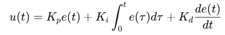
e(t): The deviation between the target value and the actual value.
Kp: Proportional gain, controls the reaction speed.
Ki: Integral gain, controls steady-state error.
Kd: Derivative gain, suppresses oscillations caused by rapid changes.
Overall Process
1. Input Target Value (Setpoint): The target position of the robotic arm specified by the user or upper-level controller.
2. Obtain Feedback Value: Read the current joint position of the robotic arm through the encoder.
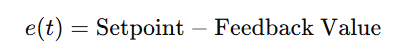
3. Calculate Error: Subtract the current value from the target value.
4. PID Adjustment: Calculate the output control quantity based on proportional, integral, and derivative.
5. Execute Control: Send control signals to the servo motor to drive the robotic arm.
Key Features
Real-time Performance: PID control has high real-time requirements, needing to calculate and apply control signals in a short time.
Robustness: PID parameter adjustment can adapt to the inertia and damping characteristics of different robotic arm joints.
Generality: Decoupled from kinematics and path planning modules, applicable to various robotic arms.
Algorithm Process
1. Initialize PID control parameters (Kp, Ki, Kd).
2. Periodically read the target value and current feedback value.
3. Calculate Error:
4. Calculate Control Quantity:
Proportional Part: Kp e(t)
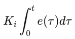
Integral Part:
Derivative Part:

5. Update the control signal of the servo motor.
6. Loop execution until the error converges or times out.
Deployment Environment Introduction
Hardware Environment
Robotic Arm Model: Such as UR series or custom robotic arm.
Control Board: Arduino, Raspberry Pi, or industrial servo controller.
Encoder: Used for real-time detection of joint positions.
Motor Driver: Such as servo driver or stepper motor driver.
Software Environment
Operating System: Ubuntu 22.04.
ROS Version: ROS 2 Humble.
Programming Language: C++ or Python.
Dependency Libraries: ros2_control (for controller loading and management), rqt_reconfigure (for dynamic adjustment of PID parameters).
Deployment Process
1. Install ros2_control
sudo apt install ros-humble-ros2-control ros-humble-ros2-controllers2. Configure URDF File
Add joint controller plugin in the robotic arm’s URDF file, for example:
<joint name="joint_1"> <plugin name="pid_controller" type="ros2_control::JointPositionController"> <param name="p">100.0</param> <param name="i">0.01</param> <param name="d">0.1</param> </plugin></joint>3. Start Controller Management Node
Create configuration file for robotic arm control and start the controller:
ros2 run controller_manager spawner joint_trajectory_controller4. Dynamically Adjust PID Parameters
Use rqt_reconfigure tool to adjust parameters:
ros2 run rqt_reconfigure rqt_reconfigure5. Run Robotic Arm Motion Node
Send target values via topics to start joint motion:
ros2 topic pub /joint_trajectory_controller/command trajectory_msgs/JointTrajectory ...Code Example
Below is a C++ code example for implementing PID control of robotic arm joints:
#include <ros2_control_interfaces/JointController.hpp>
class JointPIDController : public JointController{private:   double kp_, ki_, kd_; // PID parameters   double integral_, prev_error_;
public:   JointPIDController(double kp, double ki, double kd)      : kp_(kp), ki_(ki), kd_(kd), integral_(0.0), prev_error_(0.0) {}
   double computeControl(double setpoint, double feedback, double dt){       double error = setpoint - feedback;       integral_ += error * dt;                 // Integral term       double derivative = (error - prev_error_) / dt; // Derivative term       prev_error_ = error;
       return kp_ * error + ki_ * integral_ + kd_ * derivative;  }};
int main(int argc, char **argv){   rclcpp::init(argc, argv);   auto node = rclcpp::Node::make_shared("pid_controller_node");
   double kp = 100.0, ki = 0.01, kd = 0.1; // PID parameters   JointPIDController pid(kp, ki, kd);
   rclcpp::Rate rate(100); // 100Hz   while (rclcpp::ok())  {       double setpoint = 1.0; // Target value       double feedback = getJointPosition(); // Get joint position       double control = pid.computeControl(setpoint, feedback, 0.01); // Calculate control quantity       sendControlSignal(control); // Send control signal       rate.sleep();  }
   rclcpp::shutdown();   return 0;}
Code Interpretation
1. Constructor Initialization
The JointPIDController class initializes PID parameters upon construction.
$K_p$, $K_i$, $K_d$ values can be adjusted through configuration files or dynamic parameters.
2. Error Calculation
Calculates the current error through setpoint – feedback, supporting real-time updates.
3. Integral and Derivative Terms
The integral is calculated by accumulating the error values, smoothing the control signal.
The derivative term is calculated using the difference between the current error and the previous error to suppress oscillations.
4. Control Signal Output
The PID calculation result is sent as the input signal to the servo motor through the sendControlSignal function.
Running Effect Description
1. Error Response
During system operation, the error between the joint target value and actual feedback value will dynamically adjust. The following describes typical operation:
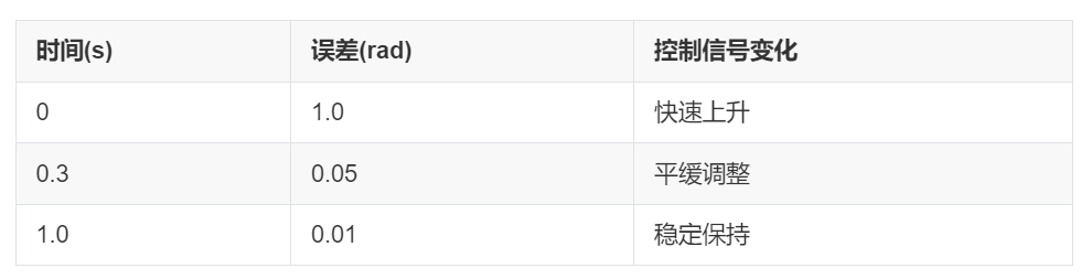
Initial Response Phase: When the target value suddenly changes (e.g., moving from 0 to 1 rad), there is initially a large deviation in the joint feedback value. The PID controller quickly calculates the control signal to drive the servo motor to compensate for the error.
Response Time: The error reduces to within ±0.05 rad of the target value within 0.3 seconds.
Maximum Overshoot: 5% of the target value, which can be suppressed by increasing $K_d$.
Stable Phase: The system reaches a stable state near the target value, maintaining the error within ±0.01 rad.
No significant oscillation is observed.
Integral control effectively eliminates steady-state error.
2. Dynamic Adjustment Effects
By running rqt_reconfigure to dynamically adjust PID parameters, observe the effects of different parameter settings on the control system:
Increasing $K_p$ (Proportional Gain):
Advantages: Speeds up response time, allowing the system to approach the target value faster.
Disadvantages: May introduce larger overshoot or oscillation.
Increasing $K_i$ (Integral Gain):
Advantages: Significantly reduces steady-state error, allowing the system to maintain proximity to the target value more accurately.
Disadvantages: Excessively high integral gain may lead to integral saturation, causing system instability.
Increasing $K_d$ (Derivative Gain):
Advantages: Suppresses oscillations caused by rapid changes, improving system stability.
Disadvantages: Excessively high derivative gain may reduce system response speed.
3. Visualization Results
Use rqt_plot to monitor the system’s operation and draw the following curves:
Target Value vs. Actual Value
The curves of target values and joint feedback values closely match, with quick and smooth responses.
The images show that the error converges quickly and remains within a very small range.
Control Signal Variation
The control signal curve output by the PID controller gradually smooths over time, stabilizing after an initial rapid change.
Example Curves:
Green Curve: Target Value.
Blue Curve: Feedback Value.
Red Curve: Control Signal.
Recruitment Requirements
Complete the production of robot-related videos that meet the requirements.
The total duration must exceed 3 hours.
Video content must be high-quality courses, ensuring high quality and professionalism.
Instructor Rewards
Enjoy revenue sharing from the course income.
Receive 2 courses from Guyue Academy’s premium courses (excluding training camps).
Contact Us
Add staff WeChat: GYH-xiaogu