Before learning about low power consumption in PIC microcontrollers, let’s briefly go over some basic knowledge and concepts related to low power consumption.
Power (Watts) = U (Volts) * I (Amperes)
Energy (Joules) = U (Volts) * I (Amperes) * t (Seconds)
Charge (Coulombs) = I (Amperes) * t (Seconds)
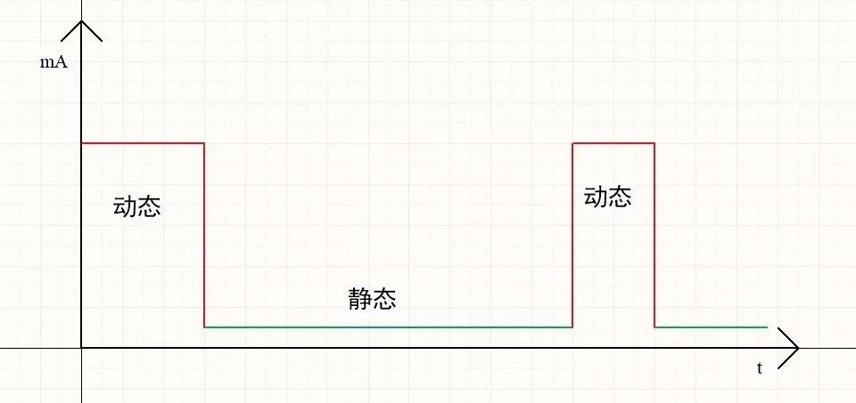
Power consumption can be divided into dynamic (active) power and static (sleep) power.
Average power consumption = (Dynamic power x Dynamic time + Static power x Static time) / (Dynamic time + Static time)
From this, we can draw some conclusions: to reduce average power consumption, we can focus on the following aspects:
Reduce dynamic (operational) power;
Reduce dynamic (operational) time;
Reduce static (sleep) power;
Increase static (sleep) time.
Having understood this much, I will also share some of my accumulated experiences at the end. Now, let’s officially start learning about low power consumption in PIC microcontrollers.
The PIC16F184xx has three power-saving modes: Doze, Idle, and Sleep. Power consumption: Doze > Idle > Sleep.
Doze Mode
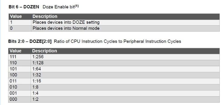
Energy saving is achieved by reducing CPU operations and memory access, while peripherals and the system clock remain operational. Enter Doze mode by setting DOZEN=1, and determine the number of cycles to execute one instruction using the DOZE[2:0] register.
Idle Mode
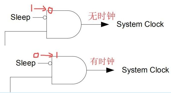
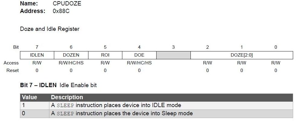
Idle mode differs from Doze in that both the CPU and memory are turned off. Enter Idle mode by setting IDLEN=1 and then executing the SLEEP instruction. Here, let’s recall the content from the first article about the clock: when the SLEEP instruction is executed, the system clock is no longer available, and the CPU stops working; whereas in Doze mode, the SLEEP instruction is not executed, so the system clock is still present, and the CPU can be considered to be in a low-speed mode.
Sleep Mode
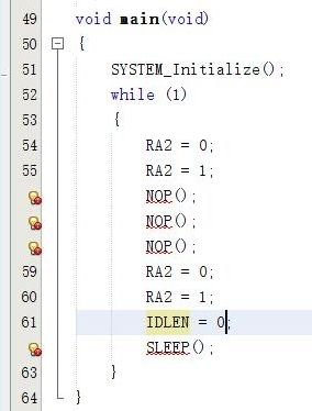
In Sleep mode, the CPU and most peripherals are turned off, making it the most power-efficient mode. Enter Sleep mode by setting IDLEN=0 and then executing the SLEEP instruction.
Practical Application
I looked for low power-related configuration options in MCC but couldn’t find any, so it seems I can only operate in the program. In the previous IO program, the clock is LFINTOSC, with a 512 prescaler, and RA2S is output. The program is as follows. The phenomenon is that the LED blinks twice and then remains off, indicating that it has entered sleep mode. The SLEEP(); instruction can also be used as asm(“sleep”);.
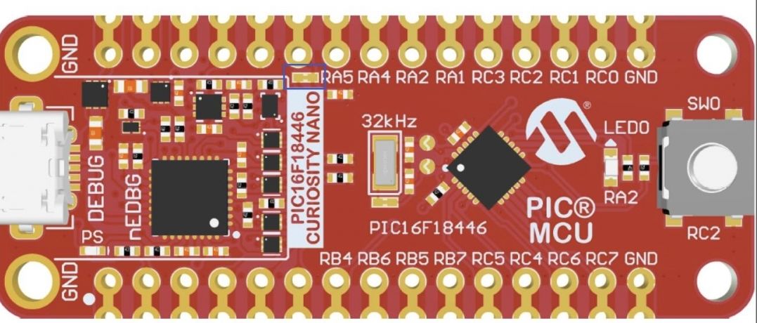
Next, I will measure the power consumption during sleep. Some modifications are needed on the evaluation board; first, cut J100, which is the power supply line for the MCU. As shown in the basket position.
Then, power the MCU and connect the ammeter in series with the circuit.
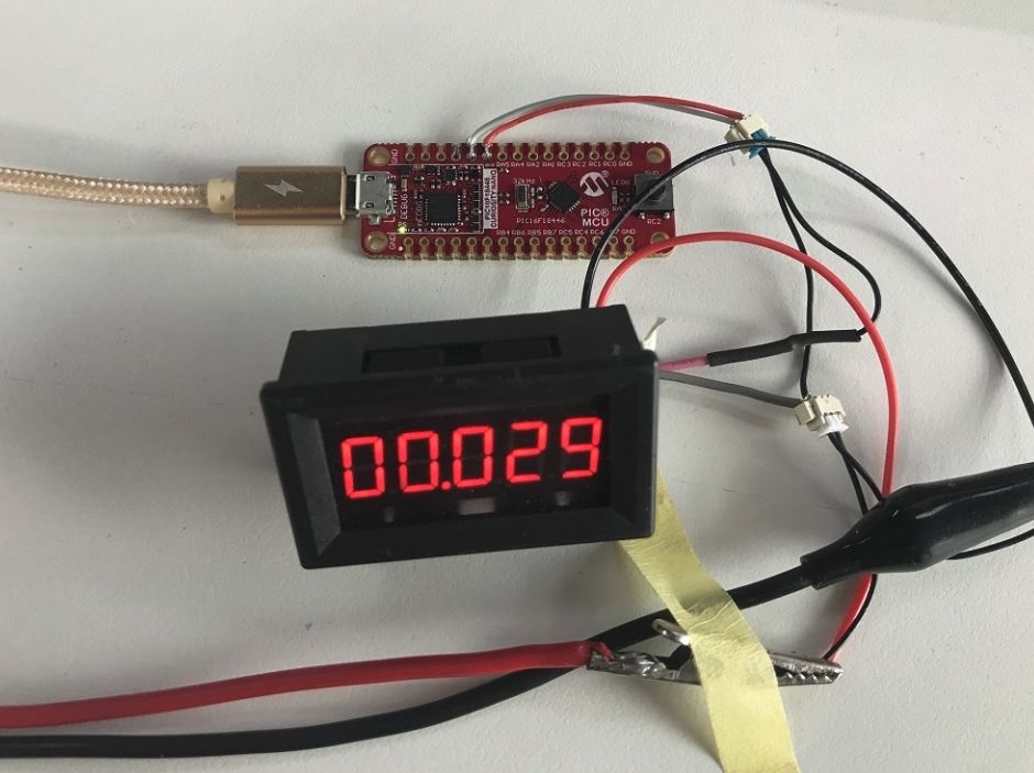
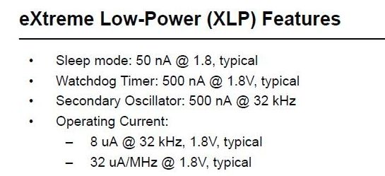
The actual measured power consumption after entering sleep is 29uA, which is far from the nA level claimed in the manual.
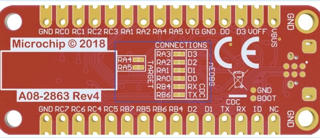
First, consider the possible current generated on the IO ports. The connected IOs are RA0, RA1, RA2, RA3, RA4, RA5, RB4, RB6, RC2, among which RA2 is connected to an LED and has been configured to output high, so it will not generate current; RC2 is connected to a button, which is disconnected and will not generate current; RA3 is for reset, with an external pull-up 10k resistor, which will generate current when the pin is low, but normally it does not, and even if it does, it is at the nA level. These three pins are retained, while all other IO connections are cut off, which are mostly connected to the debugger. As shown in the following figure, all basket wires are cut off.
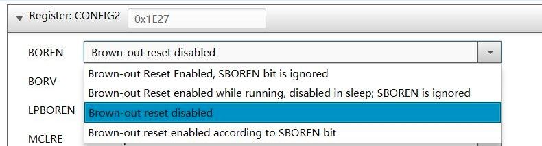
Then measure the current, and disappointingly, there was no change. Next, consider which peripherals might not be turned off. Checking the MCC configuration, I found that the watchdog WDT is not enabled, but the brown-out reset BOR is enabled. After turning off the BOR, the measured current is 24uA, which has decreased somewhat; the BOR does have some impact, but there is still a significant gap, so I will continue troubleshooting.
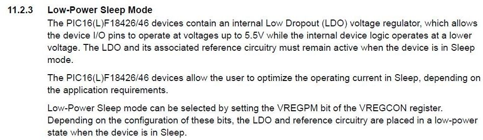
Upon carefully reading the manual, I found this description: the PIC16F18446 includes an LDO that allows the IO to use a maximum of 5.5V high voltage while operating internally at a lower voltage. The LDO will definitely have some static current. The next section mentions that setting VREGPM can enter low power sleep mode.
Detailed description of the register

After adding VREGPM=1; to the program and then executing the SLEEP instruction, this time the measured current is below 1uA, which is indeed a significant improvement. This result has reached the nA level, consistent with the values claimed in the manual.
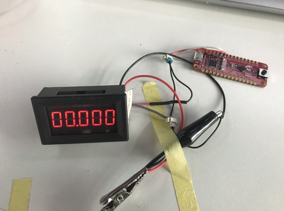
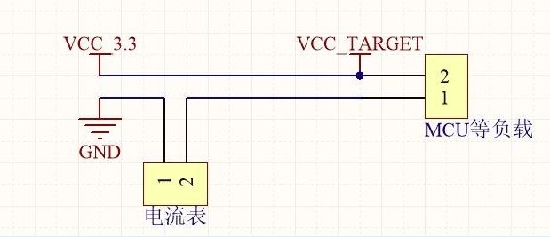
Since my ammeter’s range only goes up to 1uA, I will use a different method to measure. As shown in the schematic below.
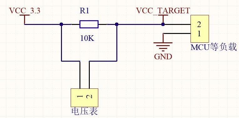
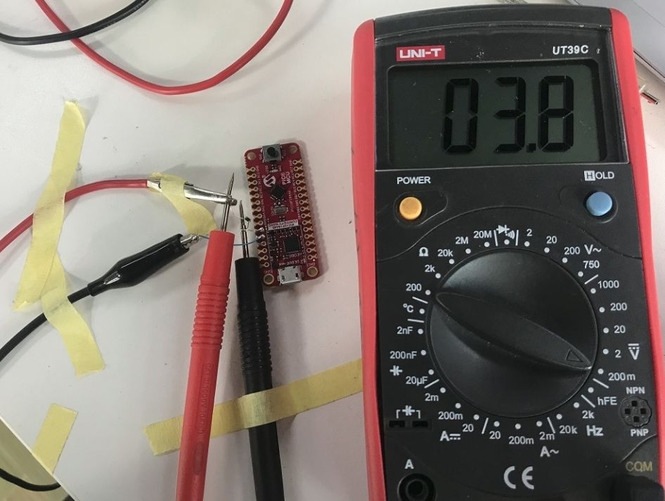
The measurement result is 3.8mV, and the detection resistor R1 is 10kΩ, so I=U/R, thus the current is 380nA.
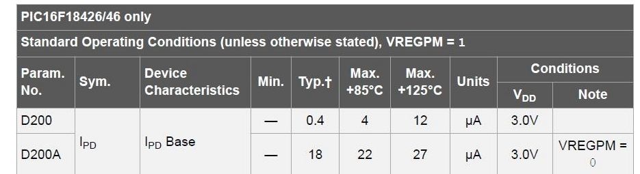
In the electrical characteristics, I saw the following segment, which corroborates our test: when VREGPM=1, the typical power consumption in sleep mode is 0.4uA, and the actual measured value is 0.38uA; when VREGPM=0, that is, when the internal LDO is on, the typical value is 18uA, and the actual measured value is 24uA, which is slightly higher, but within the same order of magnitude. Additionally, temperature and VDD voltage will also have some impact, which I will not delve into for now. Thus, the minimum power consumption for low power applications has been achieved, and I will add my own functions and logic based on requirements later.
This has already taken up some space, and there is still some content to cover, including examples of Idle and Doze modes, as well as some of my experience sharing. I think it would be better not to make the post too long for the forum, as it would be a burden for both readers and myself. So, I will stop here for this week, and we will see the second part of low power consumption in PIC next week. O(∩_∩)O
(This article is excerpted from the 21ic forum, author: 21ic user yongruru)