PCB-Level Thermal Design (Part 2)
Recently, I have been busy with work and haven’t updated for a long time. Let’s continue with the design concepts of PCB thermal design. This issue mainly focuses on transient thermal resistance, which is an easily overlooked parameter. When estimating the junction temperature of power devices, thermal resistance is used, and when power dissipation varies over time, transient thermal resistance must be used.
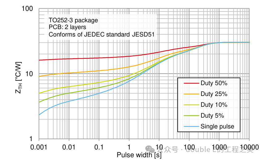
Chart Description:・ The X-axis represents Pulse width, which indicates the time power is applied to the device.・ The Y-axis shows the value of transient thermal resistance.・ The curve represents the transient thermal resistance data.・ The differences between the various curves are due to different duty cycles of the applied pulse power.
Junction Temperature Calculation
Step 1: Check the power pulse width and duty cycle applied to the power device, and record the values.Step 2: Using the values recorded in the previous step, read the transient thermal resistance value from the chart.Step 3: Use the following formula to calculate the junction temperature [TJ].
Where, : Ambient temperature [℃] : Transient thermal resistance from junction to ambient [℃/𝑊]𝑃 : Power dissipation of the device [𝑊]
Example 1
1. Check the pulse width generated by high power in a short time and record the value. The image shows a pulse width of 1m 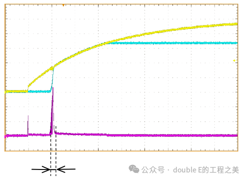 2. Using the values recorded in the previous step, read the transient thermal resistance value from the chart. Transient thermal resistance 𝑍𝑇𝐻 = 2.3 [℃/𝑊]
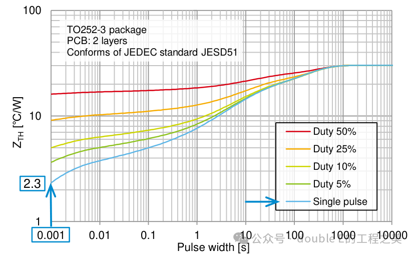
3. Use the following formula to calculate the junction temperature [TJ].= 60 [℃]𝑃 = 10 [𝑊] (obtained through calculation or measurement)= 60 + 2.3 × 10 = 83 [℃]
Example 2
When the circuit operates in an ON-OFF intermittent manner, use the [Duty xx%] curve to estimate the junction temperature.
1. As shown, pulse width = 1 [𝑠], duty cycle = 10 [%]
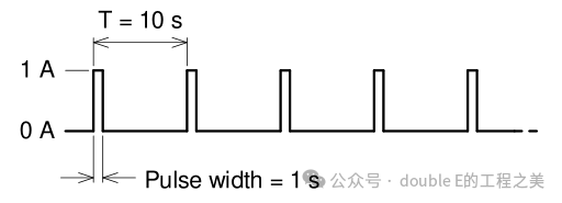
2. Using the values recorded in the previous step, read the transient thermal resistance value from the chart. Transient thermal resistance 𝑍𝑇𝐻 = 9.4 [℃/𝑊]
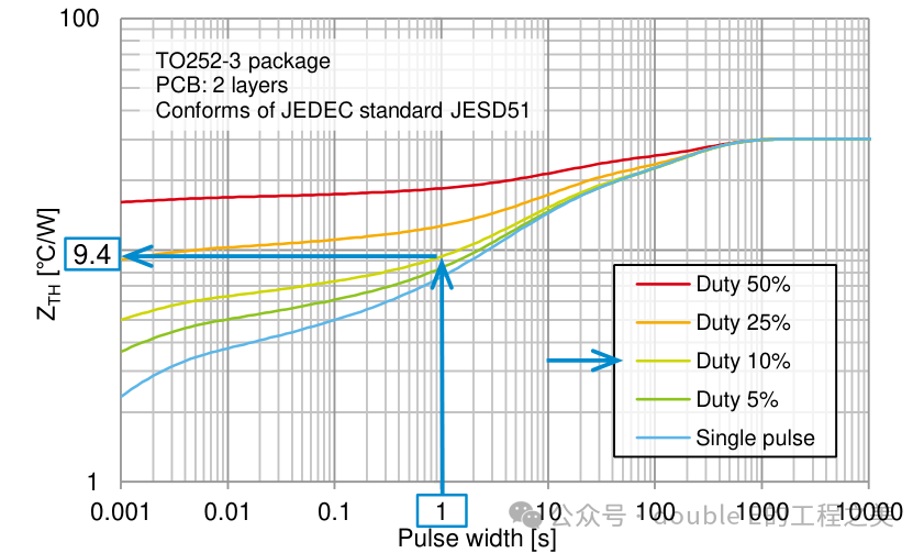
3. Use the following formula to calculate the junction temperature [TJ].= 60 [℃]𝑃 = 2 [𝑊] (obtained through calculation or measurement)= 60 + 9.4 × 2 = 78.8 [℃]
Example 3
When the circuit’s operating state is continuously changing in an intermittent manner, use the combined values of steady-state and transient operation to estimate the junction temperature.
1. As shown, pulse width = 1 [𝑠], duty cycle = 25 [%]
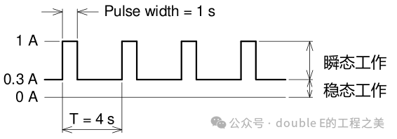
2. Using the values recorded in the previous step, read the transient thermal resistance value from the table. Then, read the steady-state thermal resistance [θJA]. The value of θJA corresponds to the number on the right side of the curve. Transient thermal resistance 𝑍𝑇𝐻 = 13 [℃/𝑊], steady-state thermal resistance 𝜃𝐽𝐴=30 [℃/𝑊]
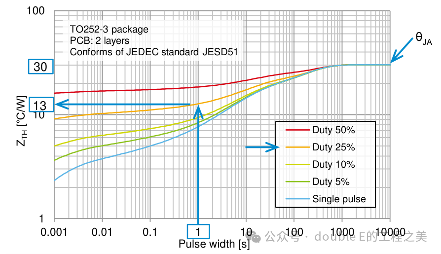
: Thermal resistance from junction to ambient [℃/𝑊] : Power dissipation of the device during steady-state operation [𝑊]Then, calculate the temperature rise during transient operation.
: Transient thermal resistance from junction to ambient [℃/𝑊] : Power dissipation of the device during transient operation [𝑊]Calculate using the following formula.
: Ambient temperature [℃]
Summary and Thoughts
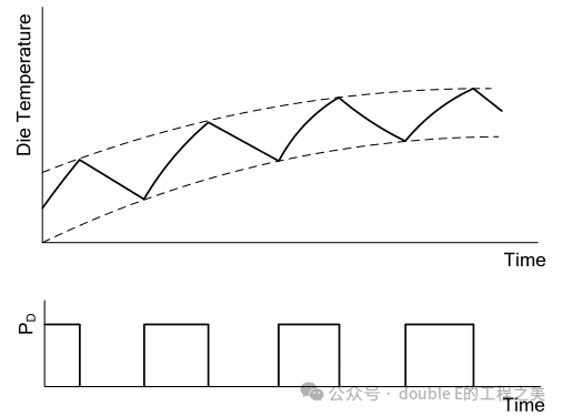
If power is continuously dissipated, a balance will be reached between heat generation and dissipation, stabilizing TJ. The thermal capacity of the device will store some thermal energy. The steady state is determined by thermal resistance, which is related to the transistor and its thermal environment.
As shown in the figure, when power dissipation stops, the device will cool down, and the heating and cooling patterns are the same. However, if power dissipation stops before the transistor temperature stabilizes, the peak value of TJ will be lower than that reached under the same continuous power dissipation level.
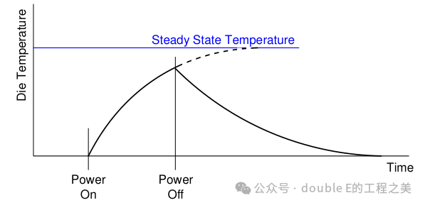
As shown in the figure, if the second pulse is the same as the first pulse, the peak temperature reached by the device at the end of the second pulse will be higher than that at the end of the first pulse. Subsequent pulses will accumulate until the temperature reaches a new steady value. Under these stable conditions, the device’s temperature will fluctuate around the average value.
Thermal resistancereflects the temperature rise caused by limited-time power pulses. This thermal resistance provides a simple method to estimate the junction temperature of the device under transient power dissipation conditions. The transient thermal resistance tends to equal the thermal resistance under continuous power dissipation conditions, which can be estimated using the following formula:As shown in the figure, as the pulse duration increases, and approach equality.
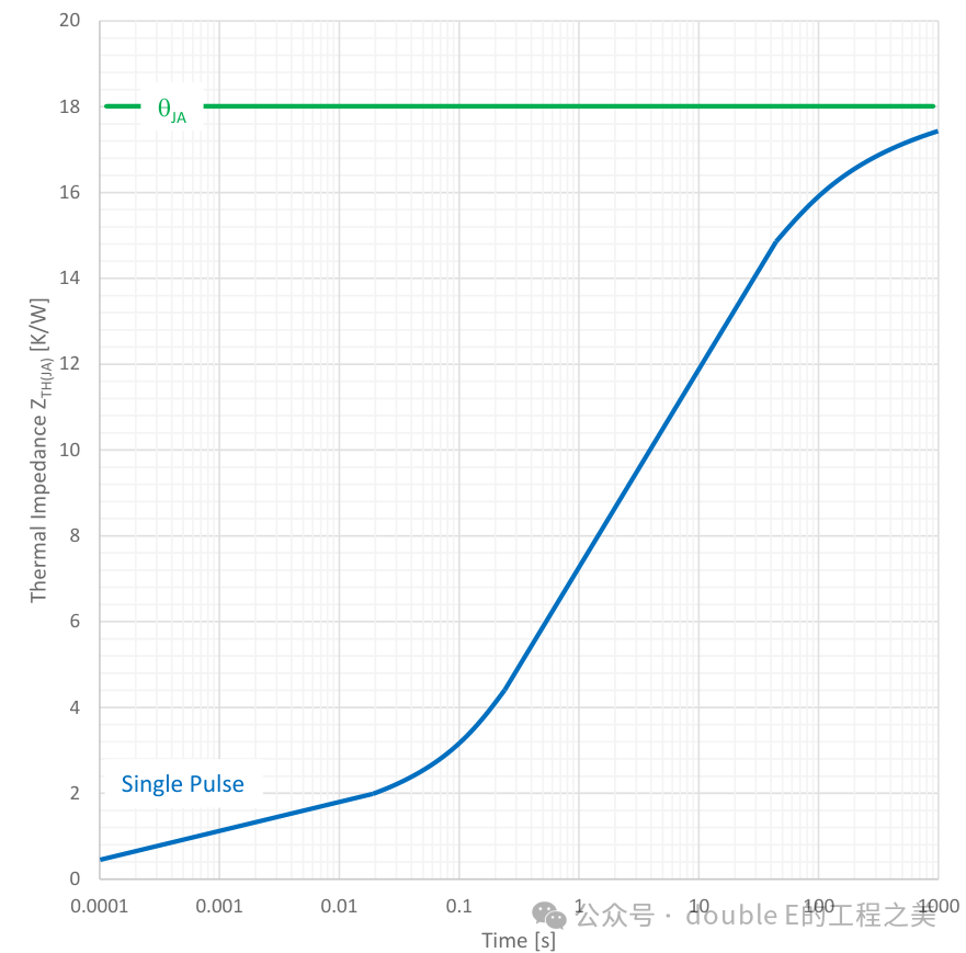
The junction temperature affects many operating parameters and the lifespan of the device. One of the most challenging aspects of designing high-power circuits is determining whether a specific device can meet the relevant application requirements. Effective transient thermal resistance is influenced by many factors, including copper area and layout, heat from adjacent devices, thermal mass of adjacent devices on the PCB, and airflow around the device. To accurately estimate the temperature rise, it is best to measure thermal resistance directly in the application circuit.