Background
Currently, the mainstream media in embedded storage devices used in mobile terminals (here mainly referring to UFS/eMMC, collectively referred to as “embedded storage devices”) is still TLC. However, the higher storage density of QLC has already been productized, for example, some data centers (read-intensive applications) have already deployed QLC storage devices. QLC can bring lower costs to storage devices, and it is inevitable to introduce QLC in consumer-grade embedded storage devices in the future.
However, compared with the current mainstream TLC, QLC has significant differences in performance and lifespan, as seen in the comparison of performance and lifespan between a certain manufacturer’s TLC and QLC below.
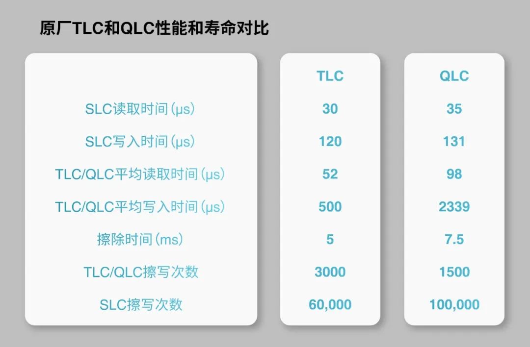
(Table 1: Comparison of performance and lifespan between a certain manufacturer’s TLC and QLC)
Therefore, to apply QLC in embedded storage devices, we must first solve the two major problems of poor performance and short lifespan.
Although QLC has less than 1/4 of the write performance of TLC, currently consumer-grade solid-state storage products have mature SLC cache mechanisms that can ensure users have relatively good burst write performance (the performance of writing to SLC). Since embedded storage devices have relatively ample idle time, they can use this idle time to move data from SLC to QLC; as long as it is not in a heavy write scenario, users generally do not perceive this part of QLC’s write performance.
However, once data is written to QLC, compared to TLC, user read performance deteriorates. To address this poor read performance, one solution is to write hot data (frequently read) back to SLC, but this undoubtedly increases the complexity of the device, and the data migration brings additional write amplification, which exacerbates the already short lifespan of QLC.
If performance issues can be solved or alleviated by SLC, then for the lifespan issue of QLC, before the introduction of partition storage, possible solutions include: the user-side using F2FS file system and using data sharding.
F2FS file system transforms random writes into sequential writes, which reduces write amplification caused by internal garbage collection of the storage device, but the garbage collection of the F2FS file system itself may bring additional writes to the storage device. Overall, the write amplification caused by the F2FS file system may not necessarily decrease.
Data sharding requires cooperation between the host and the device: the host side identifies hot and cold data, and the device side stores them in different flash blocks based on their heat level. Data sharding can reduce write amplification to some extent, but the specific benefits depend on the ratio of hot to cold data, so there are certain limitations.
Today, we will introduce the ultimate trick to reduce write amplification — Partition Storage, which can eliminate the lifespan differences between QLC and TLC, and also improve the performance of storage devices, making it possible to apply QLC to embedded storage devices.
What is Partition Storage?
The concept of partition storage originated from SMR HDDs. SMR stands for “Shingled Magnetic Recording,” an important technology used to increase capacity and reduce the cost per TB of hard drives. SMR hard drives divide the hard drive into several zones, and each zone must be written sequentially, otherwise, data overwriting may occur, leading to data loss of previously written data.
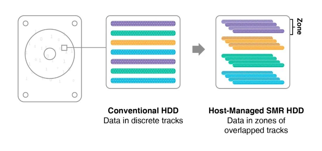
(Figure 1: SMR HDD)
The logical space of partition storage devices is divided into several contiguous partitions, which can only be written sequentially. Each partition has a write pointer to track the next write position. Data in a partition cannot be overwritten; it must first be erased using a special command (zone reset).
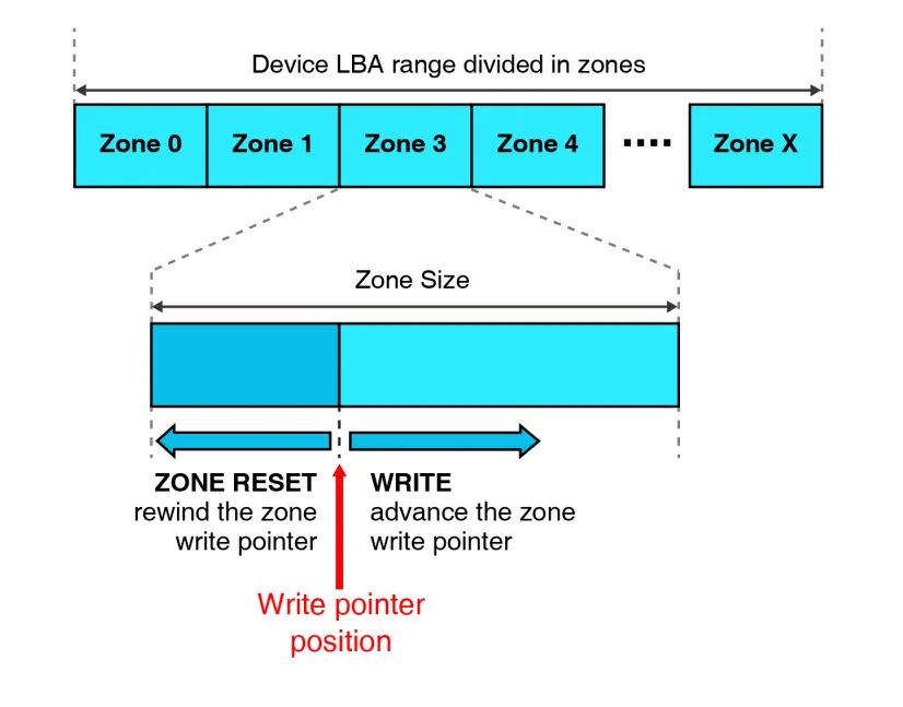
(Figure 2: Concept of Partition Storage)
In addition to HDDs, flash-based solid-state storage devices also prefer sequential writes because sequential write performance is better and the resulting write amplification is smaller. “Enabling host-side sequential writes” has always been a dream for solid-state storage devices, and with the support of SMR HDDs, the partition storage ecosystem is becoming increasingly complete. NVMe has also established the ZNS (Zoned Namespace) standard, allowing SSDs to realize this dream.
Benefits of Partition Storage
One major benefit of partition storage is that it can eliminate garbage collection within the storage device. Garbage collection in storage devices leads to two main problems: first, it introduces write amplification, reducing the lifespan of the storage device; second, if garbage collection occurs simultaneously with host read/write, the garbage collection operation will affect host read/write performance.
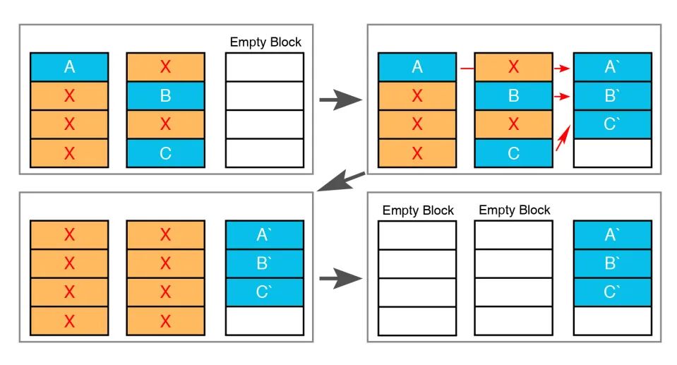
(Figure 3: Example of Garbage Collection)
Principle of Garbage Collection: To free up idle flash blocks, effective data A, B, and C need to be moved from the source flash block to a new flash block, and the internal data movement introduces write amplification. Write amplification = amount of data written to flash / amount of data written by the host. The larger the write amplification, the more severe the wear on the flash.
How can Partition Storage eliminate garbage collection in storage devices?
If the partition size is an integer multiple of the flash block size of the storage device, then the data of one partition will be written into an integer number of flash blocks within the storage device. Since partitioning does not allow overwrite writing, the data of a partition can only be invalidated as a whole, which means that the corresponding flash blocks of that partition are also completely invalidated (there is no valid data above), thus the storage device can reclaim the flash blocks without garbage collection — it only needs an erase operation.
Traditional garbage collection requires moving valid data on flash blocks, leading to write amplification. Additionally, to reduce write amplification and accelerate garbage collection, storage devices usually reserve some flash space (commonly referred to as OP) to reduce the number of valid data on flash blocks. Now, due to the absence of garbage collection in partition storage devices, there is no write amplification, and this part of OP can also be saved (cost savings).
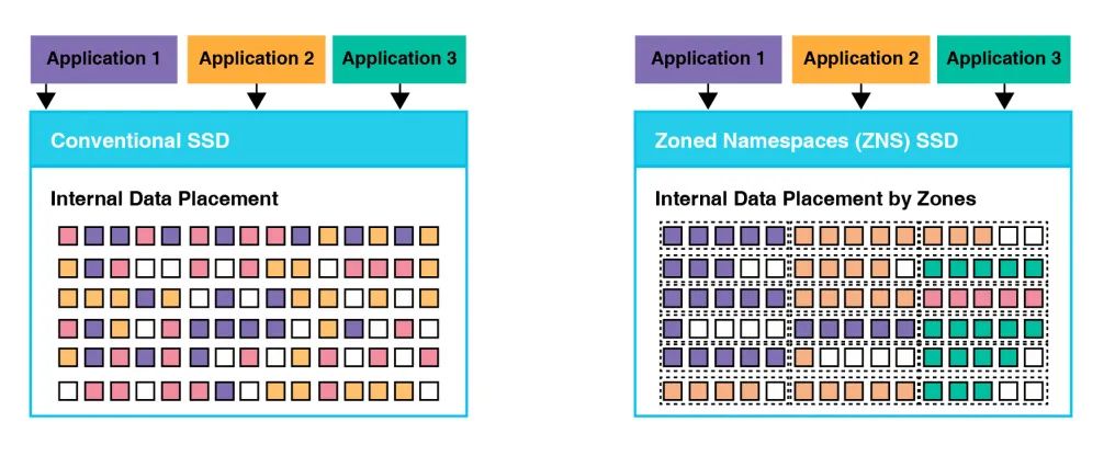
(Figure 4: Comparison of traditional SSD data storage and partition SSD data storage)
Another major benefit of partition storage is that it greatly reduces the size of the mapping table, thereby improving system performance and reducing storage device costs.
Traditional flash-based storage devices generally map at a granularity of 4KB logical blocks, and their L2P mapping table (mapping from logical address to physical address) size is generally 1/1024 of the storage device capacity, for example, a 512GB UFS device has an L2P mapping table size of 512MB. Enterprise SSDs generally come with DRAM of corresponding size to store the runtime L2P mapping table, for example, a 512GB enterprise SSD needs at least 512MB of DRAM; while consumer-grade storage devices in the industry generally do not have DRAM for cost reasons. They use a small SRAM cache in the controller for part of the L2P mapping table, while the vast majority of the L2P mapping table is stored in flash, and the firmware loads the mapping relationship data from flash to the controller’s SRAM as needed. This DRAM-less storage device, compared to storage devices with DRAM, lacks the cost of DRAM, but performance will undoubtedly be greatly reduced, because the size of the controller’s SRAM is limited, and for random read scenarios, the mapping table cache hit rate is very low. The firmware often needs to first load the mapping relationship from flash and then read user data based on the obtained physical address, meaning that reading a piece of data requires accessing flash multiple times, which definitely slows down the reading performance compared to accessing flash only once.
The root cause of the problem is that the mapping granularity of traditional storage devices is too fine, leading to a huge mapping table. In contrast, for partition storage devices, we can use the partition size as the mapping granularity. Assuming a partition size of 128MB, a 512GB device has 4096 partitions, and each partition’s corresponding physical address is represented by 4 bytes, then the entire L2P mapping table is only 16KB! Such a small mapping table can easily be stored in the controller’s SRAM, thus saving DRAM usage in enterprise SSDs; for consumer-grade storage products, the L2P mapping table can reside in memory, eliminating the need to fetch mapping relationships from flash, allowing reading a piece of data to only require accessing flash once, which greatly accelerates random read performance.
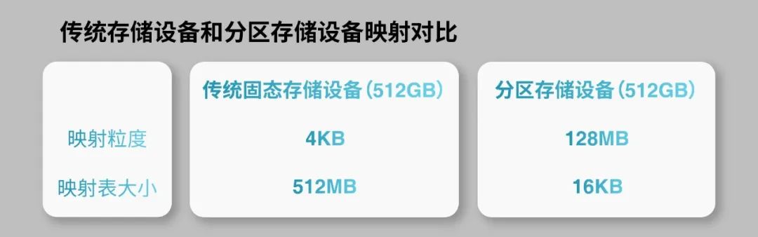
(Table 2: Comparison of mapping between traditional storage devices and partition storage devices)
Partition Storage Empowers QLC Embedded Storage Devices
Returning to the topic of applying QLC to embedded storage devices.
In traditional embedded storage devices, garbage collection generally introduces 3-4 times write amplification, meaning that a TLC flash memory with 3000 erase-write cycles may only provide the user with less than 1000 cycles. With the use of partition storage, since there is no garbage collection, the write amplification can approach 1, meaning that a QLC with 1500 erase-write cycles provides the user with exactly 1500 cycles. This means that: traditionally, a storage device using TLC with 3000 erase-write cycles, assuming TBW is 100TB, now if using QLC, although the erase-write cycles of QLC are only half that of TLC, due to the use of partition storage, TBW can instead be increased to 150TB.
For partition storage devices, since the L2P mapping table is very small, it can be fully stored in the controller’s SRAM, allowing for quick updates and retrieval of mapping relationships, thus significantly improving system read and write performance. In traditional TLC-based embedded storage devices, when randomly reading a piece of data (4KB), due to the small L2P mapping cache (a few hundred KB), the firmware is likely to first load the L2P mapping relationship from flash, which takes about 40us, and then take about 60us to load user data from flash — the total time for random read of a piece of data is about 100us; whereas now, with partition storage-based embedded storage devices, the time to load the mapping relationship is eliminated, although reading from flash takes longer for QLC than for TLC, the total time for both is comparable.
With the use of partition storage, combined with mature SLC caching mechanisms, these two characteristics compensate for the two shortcomings of QLC — short lifespan and poor performance — making it feasible to apply QLC to embedded storage devices. Currently, the typical embedded storage device is the UFS device, and if partition storage is introduced, features like HPB and FBO in UFS can be completely discarded, which undoubtedly simplifies the design of UFS devices.
Technological Outlook for Embedded Storage Devices
In terms of front-end interface protocols, the mainstream embedded storage device for Android platforms is currently UFS devices, and it is believed that it will continue along the UFS route for a long time into the future. The UFS 4.0 protocol was released in August this year, and Samsung has also previously released UFS 4.0 storage devices.
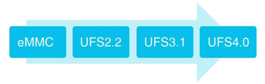
(Figure 5: Development Route of Embedded Storage Protocols)
In terms of storage media, as consumer-grade products, embedded storage devices are cost-sensitive, and with the maturity of QLC flash memory, QLC will inevitably be applied to future embedded storage devices. Both manufacturers and consumers need to be mentally prepared for this. In fact, earlier this year (2022), Kioxia has already released a UFS 3.1 product based on QLC.
To ensure that consumers can use QLC in embedded storage devices with confidence, relevant technologies need to address the issues of poor reliability, short lifespan, and poor performance of QLC media. Therefore, in terms of technological trends, on one hand, the error correction capability of embedded storage controllers needs to become stronger; on the other hand, technologies like data sharding and partition storage that can reduce write amplification will also be introduced to compensate for the short lifespan of QLC.
Currently, JIANGBOLONG has a rich lineup of embedded storage products based on mainstream 3D TLC flash memory, ranging from eMMC to high-performance UFS 3.1, from consumer-grade storage to automotive-grade storage, with a comprehensive product matrix. At the same time, the company is also considering how to apply higher density QLC to embedded storage products and is conducting relevant technological research and development work. In the future, JIANGBOLONG will continue to bring customers more embedded storage products that exceed expectations.
– Previous Reviews –
Digital Peak Manufacturing, Jiangbolong Zhongshan Phase II Topped Out, Creating an 110,000 Square Meter Enterprise-Level Storage Dedicated Line
CES 2023 | New Trends in Storage from Technology Trends
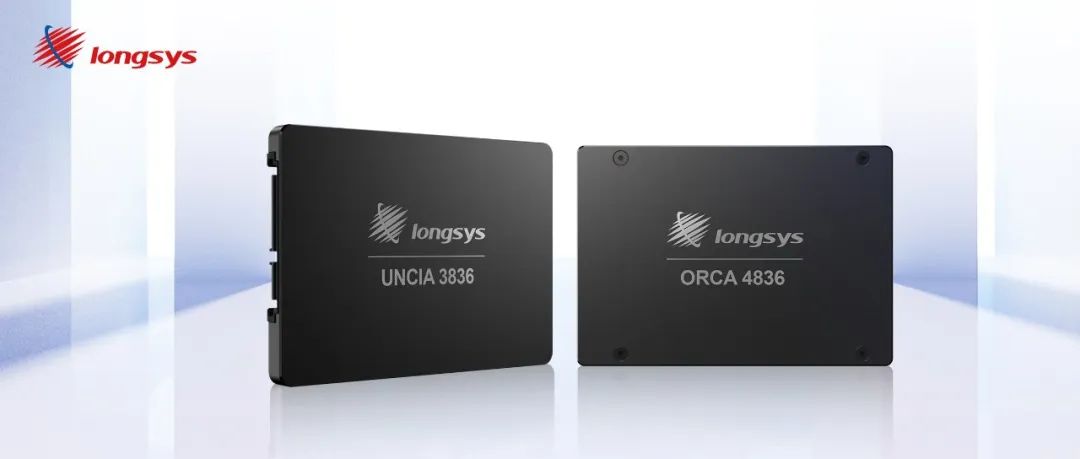
A New Leap! Jiangbolong’s First Enterprise SSD Debuts
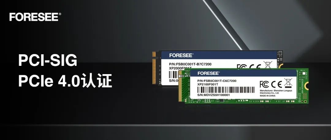
FORESEE PCIe Gen4 SSD Series Products Pass PCI-SIG Compatibility Certification