Some online monitoring systems for devices are either poorly constructed or updated without strict supervision, failing to constrain manufacturers according to sensor installation standards. This results in issues such asincorrect sensor installations and offline inspection personnel not placing sensors according to specified measurement points, leading to collected data that does not accurately reflect the operational status of the equipment, which affects monitoring effectiveness.
Typical Errors
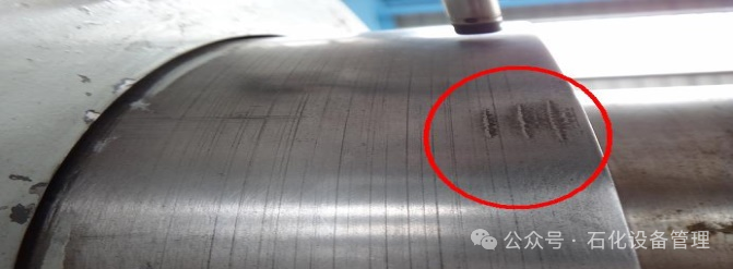
Displacement sensors are installed with obvious defects and scratches on the vibration measurement band, and there is significant mechanical deviation. The rigidity of the fixed bracket is insufficient, causing distortion in vibration values.
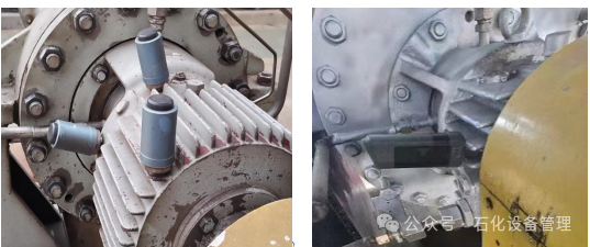
The acceleration sensors are not installed as required. They are incorrectly installed on the bearing box cooling fins, motor fan covers, and pump fan covers.
Influencing Factors
Material of the measured body: When the measured body is made of ferromagnetic materials (such as ordinary steel, structural steel, etc.), the magnetic effect reacts against the eddy current effect, reducing the sensitivity of the sensor. When the measured body is made of weakly ferromagnetic materials (such as copper, aluminum, alloy steel, etc.), the magnetic effect is weak, and the sensor’s sensitivity needs to be higher.
Surface flatness of the measured body:The surface of the measured body should not have defects such as protrusions, holes, scratches, or grooves. The roughness requirement for vibration measurement surfaces is between 0.4um and 0.8um; for displacement measurement surfaces, it is between 0.4um and 1.6um.
Magnetic effects on the surface of the measured body: Excessive residual magnetism on the surface caused during processing can lead to distortion in measurement waveforms.
Coating effects: Coatings effectively change the material of the measured body, and their material and thickness can affect sensitivity.
Installation Requirements
Working temperature requirements. Try to keep it away from steam seals. Generally, imported sensors should be below 180℃, and domestic ones below 120℃ (data from manufacturers). In practice, when the working temperature exceeds 70℃, the sensitivity of the sensor will significantly decrease..
Probe bracket requirements.The bracket should have sufficient rigidity to increase the natural frequency and avoid or reduce the bracket’s self-vibration when the measured body vibrates, ensuring that the sensor is perpendicular to the measured surface.
Initial gap requirements. When installing the sensor, it is essential to adjust the appropriate initial gap, draw the corresponding characteristic curve, and when using the sensor, carefully study the accompanying calibration certificate and analyze the characteristic curve. Generally, the larger the sensor diameter, the larger the measured gap.
Displacement Sensors
1. Radial vibration measurement
The diameter of the shaft should be more than three times the diameter of the probe. The installation position should be as close to the bearing as possible. Each measurement point should install two sensor probes simultaneously, with the two probes installed on the same plane on either side of the bearing, spaced 900±50 apart.
Shaft diameter 0~76mm, maximum distance 25mm
Shaft diameter 76~510mm, maximum distance 76mm
Shaft diameter greater than 510mm, maximum distance 160mm
The centerline of the probe should be orthogonal to the shaft centerline, and the surface monitored by the probe should be free of cracks or any discontinuities (such as keyways, unevenness, oil holes, scratches, etc.) within a width of 1.5 times the probe diameter on both sides of the probe centerline. There should be no sprayed metal or electroplating in this range, and the surface roughness should be between 0.4um and 0.8um.
Leave a certain range of non-conductive medium space, and when installing two or more sensors, consider cross-interference..
2. Axial vibration measurement
The measurement surface should be integrated with the shaft, centered on the probe, with a width of 1.5 times the probe’s circular ring. The installation distance from the probe to the thrust flange should not exceed 305mm.
3. Key phase measurement
When marked as a groove, the probe should be adjusted to the initial installation gap facing the complete part of the shaft; when marked as a convex key, the probe should be adjusted to the initial installation gap facing the top surface of the convex part to prevent the probe from being sheared off.
For φ5 and φ8 probes, the width of the groove or convex key should be greater than 7.6mm, the depth or height should be greater than 1.5mm (recommended above 2.5mm), and the length should be greater than 0.2mm. The key phase probe should be installed in the driving part, radially on the shaft..
Acceleration Sensors
When selecting measurement points, avoid high temperature, high humidity, air outlets, and places with drastic temperature changes as much as possible..
The maximum usable frequency range is about 50% of the sensor’s fixed natural frequency Fn, and threaded fixed installation is the best. If threaded installation conditions are not available, magnetic + adhesive fixing methods are recommended..
Adhesives generally include cyanoacrylate, magnets, double-sided tape, wax, hot adhesives, etc. Use the least amount of adhesive possible on a small thin film. The selection of measurement points should be directly on the position where the bearing vibration output is transmitted. Try to place it at the center of the bearing load area.