
Source: Network Optimization Mercenaries
Published by IoT Think Tank
Please indicate the source and origin when reprinting
—— [Introduction] ——
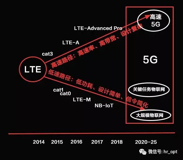
Although LTE and NB-IoT are of the same lineage, the design goal of LTE is high speed and large volume, while NB-IoT is born for the “intermittent transmission of small data” for the Internet of Things, making their directions opposite. Therefore, the LTE core network EPS is no longer suitable for NB-IoT applications and needs to be optimized.
As we all know, although LTE and NB-IoT are of the same lineage, the design goal of LTE is high speed and large volume, while NB-IoT is born for the “intermittent transmission of small data” for the Internet of Things, making their directions opposite. Therefore, the LTE core network EPS is no longer suitable for NB-IoT applications and needs to be optimized.
To enhance the transmission efficiency of small data in the NB-IoT system, the 3GPP SA2 working group began researching the CIoT EPS optimization architecture in July 2015, proposing that the CIoT EPS must support four major functions:
① Support ultra-low power IoT terminals
② Support a large number of IoT devices connected per cell
③ Support narrowband spectrum wireless access technology
④ Support enhanced coverage for IoT
And simplify functions, cutting four functions from LTE EPS:
① No emergency call service provided
② No support for traffic offloading, such as Local IP Access (LIPA) and selective IP traffic offloading
③ Only supports reselection in IDLE mode for EPS connection management, does not support handover in CONNECTED mode
④ Does not support the establishment of GBR bearers and dedicated bearers
Finally, 3GPP proposed two optimization schemes: the control plane optimization transmission scheme (C-Plane CIoT EPS optimization) and the user plane optimization transmission scheme (U-Plane CIoT EPS optimization). For IoT terminals, it must support the “control plane optimization transmission scheme” and optionally support the “user plane optimization transmission scheme”.
Control Plane Optimization Transmission Scheme
The control plane optimization transmission scheme allows small data packets to be transmitted on the control plane, with data encapsulated in control plane signaling messages in the format of non-access stratum protocol data units (NAS PDU), similar to shopping in a mall, where if a consumer only purchases a small number of items, they can check out through a designated fast lane.
This scheme reduces the overhead of control plane signaling during data transmission, thus helping to lower terminal power consumption and reduce the use of bandwidth.
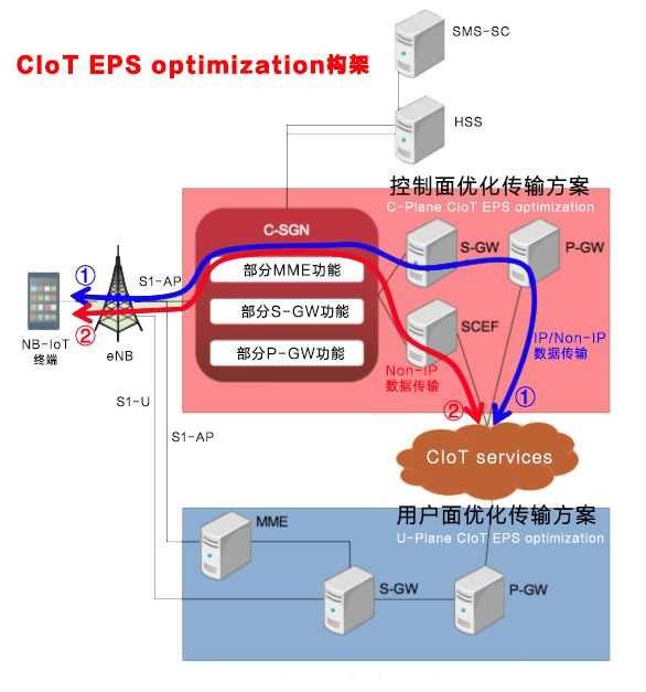
As shown in the figure above, the control plane optimization transmission scheme supports both IP data and non-IP data transmission, and the transmission path can be divided into two: ① transmitted through S-GW to P-GW and then to the application server (CIoT Services); ② connected to the application server through SCEF (Service Capability Exposure Function), which only supports non-IP data transmission.
Based on the transmission path and whether IP data transmission is supported, it can be divided into three transmission modes:
Transmission Path ① (IP Data Transmission)
The transmission path is from S-GW to P-GW and then to the application server, allowing for the rapid deployment of NB-IoT using existing IP communication technology, but the downside is low security, and since it does not go through SCEF, telecom operators still play the role of a pipeline.
Transmission Path ① (Non-IP Data Transmission)
The transmission path is still from S-GW to P-GW and then to the application server, but since there are no IP address transmission data packets, there must be a mapping relationship between the ID of the NB-IoT terminal and the IP address + port number of the AS on the P-GW to correctly transmit the data packets on the SGi interface, this method is called Point-to-Point (PtP) Tunneling technology for UDP/IP. The parameters of the tunnel, which are the destination IP address and UDP port number, need to be pre-configured on the P-GW, making the P-GW a transparent transmission node for the data transmitted between the NB-IoT terminal and the AS.
This method is highly secure and power-saving, but requires the development of new point-to-point tunneling technology.
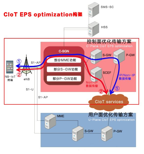
Transmission Path ② (Non-IP Data Transmission)
This means passing Non-IP data through SCEF, this path only supports non-IP data transmission and belongs to a Non-IP exclusive solution. This method has many advantages, including high security, power saving, and enabling operators to create new business value, but requires the establishment of new SCEF network element nodes and the development of new API technology.
SCEF
SCEF is a new node added to NB-IoT, which provides services to AS through API interfaces rather than directly sending data, allowing telecom operators to no longer just be a pipeline but to safely open their business capabilities to third-party service providers, enabling big data analysis for the Internet of Things to create new business value.
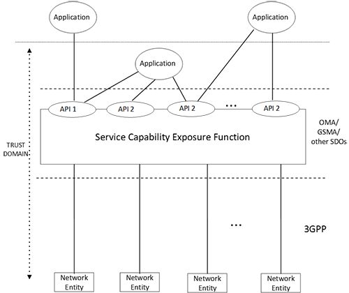
SCEF architecture is shown in the figure above. For security reasons, SCEF is placed in the operator’s trusted domain (Trust Domain) and accesses services through APIs from OMA (Open Mobile Alliance), GSMA (Groupe Speciale Mobile Association), or other standard organizations (Standardisation Bodies, SDOs). Meanwhile, the SCEF API supports various types, such as DIAMETER, RESTful APIs, and XML over HTTP, allowing SCEF to be more flexibly applied in different networks. Network Entity refers to network nodes related to HSS, MME, P-GW, PCRF, or billing and security.
C-SGN
C-SGN, or CIoT Serving Gateway Node, is a new node introduced in the control plane optimization transmission scheme. This node is a single logical entity formed by merging the minimal functions of the control plane node MME and user plane nodes S-GW and P-GW of LTE EPS. C-SGN functions can also be deployed within the existing EPS MME.
HLCom
In the control plane optimization transmission scheme, the HLCom mechanism, or Optimization to support High Latency Communication, is introduced, which caches downlink data in the S-GW. Since NB-IoT terminals intermittently receive data using technologies such as PSM and eDRX to save power, when the NB-IoT terminal is in sleep mode, the S-GW caches downlink data until the terminal is awakened and the cached data is sent to the terminal.
User Plane Optimization Transmission Scheme
The data transmission method uses user plane bearers similar to LTE EPS, but this optimization scheme introduces two new states, Suspend and Resume, at the RRC layer to adapt to the intermittent transmission characteristics of IoT data, while requiring NB-IoT terminals, eNB, and MME to store connection information to quickly resume the connection and simplify the signaling process, improving transmission efficiency.

After such optimization, the bearer can be established as needed, thus reducing terminal power consumption and supporting large-scale IoT device connections within a single cell. This scheme not only supports existing EPS functions but also supports the transmission of non-IP data through P-GW.
RRC Suspend Process
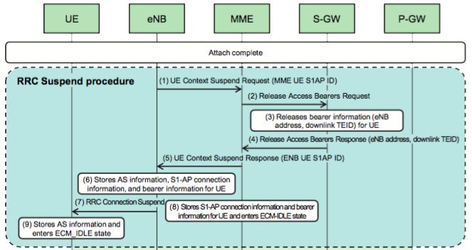
As shown in the figure above, this process is activated by eNB, releasing the RRC connection between the NB-IoT terminal and eNB, as well as the S1-U bearer between eNB and S-GW.
Steps (1) and (2):
eNB sends UE Context Suspend Request and initiates the release of bearer information related to the NB-IoT terminal through MME to S-GW.
Step (3):
S-GW releases the S1-U bearer related to the eNB and NB-IoT terminal. Specifically, S-GW only releases the eNB address and downlink tunnel endpoint identifier (TEID), while continuing to store other information.
Steps (4) and (5):
After completing the S1-U bearer release at S-GW, eNB receives the UE Context Suspend Response notification through MME.
Steps (6) and (7):
eNB stores the Access Stratum (AS) information, S1-AP connection information, and bearer information of the NB-IoT terminal and sends RRC Connection Suspend messages to the NB-IoT terminal.
Step (8):
MME stores the S1-AP connection information and bearer information for the NB-IoT terminal and enters IDLE state.
Step (9):
When receiving the RRC Connection Suspend message from eNB, the NB-IoT terminal stores AS information and enters IDLE state.
RRC Resume Process
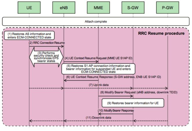
As shown in the figure above, this process re-establishes (resumes) the RRC connection between the NB-IoT UE in Suspend state and eNB, as well as the released S1-U bearer between eNB and S-GW. The Resume process is initiated and activated by the NB-IoT terminal.
Steps (1) and (2):
First, use the AS information stored during the RRC Suspend process to restore the connection with the network.
Step (3):
At this time, eNB performs a security check on the NB-IoT terminal and provides a list of restored wireless bearers to the NB-IoT terminal, synchronizing the EPS bearer status between the NB-IoT UE and eNB.
Step (4):
eNB sends UE Context Resume Request to MME to notify that the connection with the NB-IoT terminal has been safely restored.
Steps (5) and (6):
After receiving the restoration notification from eNB, MME restores the S1-AP connection information and bearer information for the NB-IoT terminal, enters CONNECTED state, and sends UE Context Resume Response message (including S-GW address and S1-AP connection information) to eNB.
Step (7):
Now the NB-IoT terminal can send uplink data to S-GW.
Steps (8) and (9):
MME sends eNB address and downlink TEID to S-GW through Modify Bearer Request message to reconstruct the downlink S1-U bearer between the NB-IoT terminal and S-GW.
Steps (10) and (11):
S-GW sends Modify Bearer Response message to MME, and then begins to transmit downlink data.
It is worth mentioning that when S-GW receives downlink data while the NB-IoT terminal is in Suspend state, S-GW will cache the data packets, while initializing the Downlink Data Notification process between S-GW and MME, then MME will page the NB-IoT terminal, thereby initiating the activation of the connection Resume process through the NB-IoT terminal.

Previous Popular Articles (Click on the article title to read directly):
-
“How Difficult Is It to Make Smart Locks for Shared Bicycles?”
-
“Cognitive Computing, Blockchain IoT, IoT Security… Those Who Understand Will Control the Future”
-
“[Heavy Release] 2017-2018 China IoT Industry Panorama Report – IoT Has Started Deep Transformation of Industries”
-
“[Heavy] IoT Industry Panorama Report, First to Open Domestic IoT Industry Two-Dimensional Perspective Panorama”
-
“A Cartoon Explains: Besides WiFi and Bluetooth, What Can the Recently Popular NB-IoT Do?”
-
“A Cartoon Explains: What Is LoRa, Which Everyone Is Talking About Behind NB-IoT?”