Follow “Avionics Technology Circle” for avionics news and technical insights~


Abstract
In response to the issue of parallel fault injection for multiple channels in the integrated testing of civil aircraft avionics systems, this study investigates the fault injection method for the ARINC429 bus and implements functional design. First, the data interaction method of the avionics relay system is analyzed, and a fault injection architecture based on the avionics relay system is designed, studying a multi-channel parallel fault injection method based on a reflective memory communication network. Then, the fault types and corresponding injection methods of the ARINC429 bus at the protocol and application layers are analyzed, and the logical design of the fault injection function is completed. Finally, a fault injection experimental platform is built based on the avionics relay system to conduct fault injection experiments. The experimental results show that the studied fault injection method can effectively achieve low-latency fault injection for multiple devices and multiple channels of the avionics bus at both the protocol and application layers, meeting the requirements for avionics system integrated testing.
Keywords
Avionics relay system, reflective memory, fault injection, ARINC429

0. Introduction
Fault injection technology is widely used in the integrated testing of civil aircraft avionics systems, providing important evidence for the reliability study of the system. When the amount of test data is large, the system may face challenges in meeting real-time testing requirements, necessitating consideration of fault injection methods that handle large data volumes and real-time requirements. The avionics relay system can achieve substantial bus data forwarding between different avionics components or hardware-in-the-loop simulators, ensuring stable operation and easy centralized monitoring, making it suitable for fault injection of bus data in integrated testing. While ensuring parallel injection of multiple channels of bus data, the system guarantees the real-time nature of fault injection.
ARINC429 data is widely used in avionics system data interaction. Fault injection for the ARINC429 bus can effectively simulate faults that occur during the operation of components, thus being applicable to integrated testing and is significant for studying the fault injection testing methods of the bus. While considering fault coverage and multi-channel parallel fault injection, the characteristics of the avionics relay system, such as low latency and strong scalability of data nodes, enable low-latency injection of various fault types across multiple devices and channels.
1. Fault Injection Method and Architecture Design for Avionics Relay System
1.1 Data Interaction Method
The avionics relay system employs reflective memory to achieve data interaction. The system configuration consists of terminals, Ethernet switches, and reflective memory switches. Terminals and configuration management computers interact through a reflective memory communication network, loading configuration files via Ethernet switches. Each terminal includes an ARINC429 bus card, Ethernet card, and reflective memory card; multiple terminals use reflective memory switches as transmission relays to realize the forwarding and monitoring of bus signals between terminals.
Reflective memory networks consist of reflective memory cards and optical fibers, characterized by stable transmission, low latency, and multiple nodes, often used to address real-time data interaction issues during simulation. Reflective memory networks meet the real-time requirements of the system for integrated testing, with high network reliability. A real-time data transmission network based on reflective memory can ensure the real-time and accuracy of test data transmission, resulting in good system testing outcomes that meet integrated testing requirements.
1.2 Fault Injection Method and Architecture Design
Considering the advantages of reflective memory and the requirement for real-time data transmission in fault injection, a reflective memory communication network is used to implement fault injection for the ARINC429 bus. The nodes of the reflective memory communication network consist of configuration management computers, fault injectors, reflective memory switches, Ethernet switches, and terminals. In the communication network, the configuration management computer serves as the human-machine interface layer, transmitting data via the Transmit Common Interface (TCI) service. Terminals and fault injectors load configuration files from the configuration management computer via FTP (File Transfer Protocol) over Ethernet. The human-machine interface layer exchanges data through optical fibers and reflective memory switches. The architecture of the fault injection reflective memory communication network for the avionics relay system is shown in Figure 1.

In the reflective memory communication network, data cache addresses are allocated for reflective memory terminal nodes and fault injector nodes. The data corresponding to each terminal and fault injector is associated with different reflective memory address segments, facilitating data interaction and fault injection through the reflective memory broadcast mechanism. The configuration management computer operates on the Windows operating system, reading reflective memory data for monitoring. The fault injector operates on the VxWorks real-time operating system, communicating with the reflective memory switch for real-time data reading and writing. During the data interaction process in the reflective memory network, the configuration management computer sends ICD (Input Configuration Document) configuration files to terminals and fault injectors, containing data content and source/destination terminal information. The configuration file for the fault injector includes fault information, and all terminals perform bus data fault injection through the fault injector. The system data flow is as follows: source terminal → reflective memory switch → fault injector → reflective memory switch → destination terminal. Based on the configuration file content, the input data from the source terminal is forwarded to the fault injector. In the fault injector, the fault information from the configuration file determines whether to proceed with fault injection. If fault injection is to be performed, the type of fault is modified according to the fault information, and the modified data is temporarily stored in the corresponding reflective memory address cache of the fault injector, awaiting retrieval by the destination terminal, thus achieving bus data fault injection. Furthermore, extending the types of faults only requires changing the configuration file content, making fault injection via the reflective memory communication network highly scalable and easy to implement.
2. Fault Types and Injection Methods for Avionics Systems
To simulate typical faults in avionics systems, fault types for the ARINC429 bus are established from the perspective of bus structure, selecting the transmission bus as the fault injection point to comprehensively cover system fault issues and improve fault injection efficiency.
2.1 Fault Types
The bus is divided into protocol and application layers according to its structure; the protocol layer is categorized based on bus protocols, while the application layer is categorized based on the specific applications of signals in different components. For bus faults, fault types are categorized into protocol layer faults and application layer faults.
The protocol layer refers to signal transmission protocols; ARINC429 bus data format is 32 bits, with each bit potentially subject to errors during transmission. Possible errors include: label errors, source/destination identification errors (SDI), data bit errors, symbol status bit (SSM) errors, and parity bit errors. These errors may occur individually or in combination.
At the application layer, faults arise based on the functional specifications of the components, leading to different types of faults depending on the functionality of the components. Common faults in avionics components include data that does not meet component specifications, such as exceeding data ranges, errors in the data itself, application data loss, and signal transmission faults caused by abnormal connections in the lines. For example, abnormal displays of received flight parameters in FMs or lost navigation signals from NAV, or erroneous azimuth data from navigation signals, such specific application layer faults can generally be categorized as either data loss or data error faults on the bus.
2.2 Fault Implementation Methods
In the reflective memory network, variables for caching the data read from the board and pending transmission are defined as phA429Data; fault caching variables are defined as phFaultData, with an initial value of FFFFFFFF; the output data cache variable is defined as phForwardData. The principle of fault injection is illustrated in Figure 2.

During the data forwarding process, the terminal board card interface simulates data transmission and reception. The configuration management computer issues configuration files that store input data in the variable phA429Data, which is then forwarded by the reflective memory switch according to the configuration file. If fault injection is initiated, the forwarded data enters the fault injector for execution. The data in variables phA429Data and phFaultData undergoes a bitwise logical AND operation, and the resulting data is stored in variable phForwardData, which is written into the corresponding cache address in reflective memory and broadcasted to other nodes. Terminals decide whether to execute read or write operations based on the configuration file, where the variable phFaultData is determined by the fault information in the configuration file. If fault injection is not performed, the data is directly forwarded to the destination terminal, achieving normal data forwarding.
2.2.1 Protocol Layer Faults
Protocol layer faults consider data format faults and signal timing faults as specified by the ARINC429 bus protocol. Based on the ARINC429 data protocol and the hardware board transmission protocol, the content of the transmitted signal is judged by reading the data from the global structure variable phA429Data in reflective memory, thereby decoding the transmitted data on the ARINC429 bus. The decoded data is then rearranged in the order of Parity, SSM, Data, SDI, and Label.
The method for implementing protocol layer data format error faults involves replacing specified placeholders in the decoded and rearranged ARINC429 data. During fault injection, the fault injector generates a fault file, locates the data position to be replaced, reverses the data at the specified positions in variable phFaultData, and subsequently performs a bitwise logical AND operation with the cached data in variable phA429Data, thus achieving data format error faults.
Signal timing faults are common issues in data transmission, where the fault content involves altering the signal period, leading to fluctuations or chaos in signal timing. This is achieved by adjusting the time interval of the task set by the fault injector for sending cached variables, controlling the timing at which variable phFaultData enters the reflective memory switch. This fault is implemented using the signal-triggered delay function TaskDelay(), measured in milliseconds. If data stacking occurs due to period changes, the stacked data can simply be discarded.
2.2.2 Application Layer Faults
Application layer fault types include data loss, data errors, and other faults. Data errors occur when the content of the data received does not match the expected content. Factors considered include the data content not conforming to the regulations for data transmission and reception between components or confusion in the data being forwarded between components, leading to errors. The implementation methods for data error faults are:
1) Randomly generate phFaultData or manually input data to assign values to phFaultData, then perform a bitwise logical AND operation with the cached data in variable phA429Data. The result alters the cache in phForwardData, achieving data error faults.
2) Change the destination terminal for data forwarding, causing components to receive data that does not belong to them, leading to incorrect data content. Each terminal’s address in the reflective memory switch is configured by the configuration management computer. When the address data changes, both the corresponding terminal and data content will change. Utilizing this feature of reflective memory, an offset address is assigned to variable phFaultData, resulting in data content errors due to the change in the destination terminal.
Data loss faults simulate the loss of signals during transmission due to reasons such as abnormal line connections, resulting in the destination terminal not receiving the expected data. This fault is implemented by assigning a large offset address to variable phFaultData in reflective memory, causing the data to be unaddressable in the reflective memory switch, leading to data loss.
3. Logic Design of Fault Injection Process
This article selects the fault injection point as the ARINC429 bus, with the data interaction method being the reflective memory communication network. During the normal data forwarding process, fault injection is performed on the bus. Terminals poll the data from the reflective memory board’s channels at the system clock rate under the VxWorks operating system. Data read/write tasks on the board are executed based on the FIFO states, scheduling the write tasks of the channel according to the first-in-first-out principle.
The process for executing system fault injection is as follows:
1) The system creates a data forwarding task and issues configuration files to terminals and fault injectors.
2) Terminals and fault injectors check the status of each channel on the board; if the FIFO status is not empty, they enable Read FIFO to start working. Terminals and fault injectors receive the configuration files; if the FIFO status is empty, multiple queries will be conducted, and the task will time out and terminate.
3) The ReceiveData function executes, and the source terminal receives data.
4) The terminal writes data into the corresponding channel address in reflective memory and broadcasts it to other nodes in the reflective memory network with the same channel address.
5) The configuration file content determines whether to perform fault injection. If fault injection is to be performed, the fault injector receives the data and executes corresponding calculations based on the fault information in the configuration file, writing the calculated results into the corresponding channel address in reflective memory and broadcasting them to other nodes in the reflective memory network with the same channel address. If fault injection is not performed, normal data forwarding occurs.
6) The terminal determines whether to forward this data. If forwarding is to occur, the destination terminal reads the data and writes it to the corresponding channel reflective memory address. If not forwarding, the process ends.
If the system is in a timeout state after multiple queries, the process will terminate to prevent the program from entering a dead loop when there is no data to forward.

4. Validation
4.1 Fault Injection Experiments
The fault injection experiment for the avionics relay system involves configuring the forwarding process of ARINC429 data for fault injection. The experiment uses a 2 km long optical fiber, with instruments including an ARINC429 bus 8-channel board and an ARINC429 bus analyzer, transmitting data at a rate of 12.5 kb/s to simulate the reception and transmission of component signals.
4.1.1 Protocol Layer Fault Injection
4.1.1.1 Data Format Error
The content of the protocol layer fault injection experiment is the data format error fault. Different fault types for data formats are set, with some experimental results shown in Table 1.

In a single experiment, the fault injection experiment for label and data word combination errors was set, resulting in the ARINC429 bus analyzer showing TX data sent as 201CB0, and RX data received as 12000004. The oscilloscope results for this experiment are shown in Figure 4.

Figure 4 shows the input signal waveform above and the output signal waveform below, corresponding to the data shown in the ARINC429 bus analyzer TX and RX. From the figure, it can be seen that there are differences in the high and low levels of Label and Data in the input and output signals, while the rest remains unchanged, consistent with the expected results of this fault experiment, indicating successful fault injection for the ARINC429 bus protocol layer.
Changing the system forwarding configuration continues to conduct experiments across different channels, with results consistently achieving fault injection, recording the latency before and after each fault injection experiment.
4.1.1.2 Signal Timing Fault
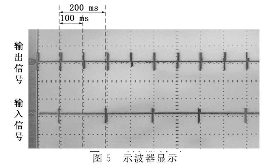
The signal timing fault injection experiment involved setting the TaskDelay() function for task timing delays, altering the signal sending interval during data forwarding. The experiment set the sending signal data period to 100 ms and TaskDelay() to 100 ms, conducting a fault injection experiment. The expected result is that the signal sending period changes to 200 ms. Using an oscilloscope to measure the waveforms before and after fault injection yields Figure 5, where significant differences are observed in the transmission periods of the upper and lower waveforms across multiple cycles. The oscilloscope measurements indicate a 100 ms phase difference between the input and output signal waveforms, with the output signal period changing to 200 ms, consistent with the expected experimental results, indicating successful signal timing fault injection. Changing the TaskDelay() function continues to yield successful fault injection across multiple experiments.
4.1.2 Application Layer Fault Injection
Application layer faults are exemplified by data content errors and data loss faults. The system terminal configuration for multi-component data interaction is shown in Table 2.

The table’s terminal configuration information is exemplified by experiment number 1: configuring terminal 1’s channel 1 to forward data 52D8A5E5 to terminal 3’s channel 8. Based on the experimental configuration table, the connection relationships for component application layers are established to simulate the transmission of bus data of real components.
4.1.2.1 Data Content Error Fault
In the data content error fault experiment, the ARINC429 bus analyzer’s TX and RX are connected to the signal sending and receiving ends, respectively. According to the terminal configuration in Table 2, the data content error faults are injected, with experimental results shown in Table 3.
For experiment numbers 1 and 4, the input data for the components are 52D8A5E5 and A5C2BB96, respectively. By swapping the destination terminals in the two experiments, the output data content of the original destination terminal is altered, leading to data content faults. The experimental results show that the output data received by number 1 is A5C2BB96, while number 4 receives output data as 52D8A5E5, indicating successful injection of data content errors. Similarly, changing the system forwarding configuration for multiple experiments consistently achieves fault injection.

4.1.2.2 Data Loss Fault
The expected result of the data loss fault experiment is that the output data is empty. According to the terminal configuration in Table 2, the experiment for data loss fault injection is conducted, with results shown in Table 4.

Changing the system forwarding configuration, multiple fault injection experiments across different channels and terminals were conducted. The fault injection functionality operates stably, indicating that the multi-channel ARINC429 bus fault injection method of the avionics relay system is genuine and effective, and the addition of fault injection functionality still ensures the stable operation of the avionics relay system, with latency recorded before and after fault injection.
4.2 Latency Analysis
Comparing the system latency during multiple fault injection experiments with the data forwarding latency under normal conditions, the differences in latency times before and after fault injection for multiple terminals and channels were calculated. Two groups of experiments were conducted for comparing different data volume fault injection and normal data forwarding:
1) Multiple terminals, single channel forwarding: The 8 channels of terminal 1 are forwarded to the 8 channels of terminals 2 to 6;
2) Multiple terminals, multiple channel forwarding: The 8 channels of terminal 1 are simultaneously forwarded to a total of 40 channels of terminals 2 to 6;
The system latency under normal data forwarding and after fault injection was measured and recorded, yielding the latency differences from multiple comparative experiments, as shown in Figure 6.

From the latency comparisons of each experimental group, it can be concluded that the maximum latency difference before and after fault injection in multiple terminals and single channel is approximately 0.05 ms, while for multiple terminals and multiple channels, the maximum latency difference is approximately 0.08 ms. The latency introduced by fault injection arises from the interactions between the fault injector and terminal data, as well as the internal computation time of the fault injector. The avionics relay system can achieve low-latency injection in multi-channel bus faults.
5. Conclusion
This article analyzes the data interaction method of the avionics relay system, studying the nodes of the reflective memory communication network, fault types of the bus, implementation methods, and fault injection logic design, achieving low-latency injection of multi-channel ARINC429 bus faults. By building a fault injection experimental testing environment, the functionality of fault injection can be realized during the data forwarding process of multiple terminals and multiple channels. Multiple experiments for different fault types consistently yield expected results for fault injection. The impact of fault injection on system latency is minimal, enabling multi-channel, low-latency fault injection that meets the real-time requirements of the system, with strong scalability of fault types, applicable to other types of buses, providing a feasible method for testing and fault diagnosis in avionics systems.
(This article is selected from Computer Measurement and Control by Fan Zhiyong, Li Ji, Liu Tao, affiliated with the Engineering Technology Training Center of Civil Aviation University of China and the School of Electronic Information and Automation of Civil Aviation University of China. This article is reprinted solely for the purpose of disseminating knowledge. If there are any copyright issues, please contact us promptly!)
AAS2024
2024 China Civil Aviation Onboard and Software Conference
To accelerate the high-quality leapfrog development of onboard systems for civil aircraft, the 2024 China Civil Aviation Onboard and Software Conference will be held in Shanghai on November 26-27.
AAS2024

For more inquiries, please contact us
AIMME | Ms. Yang
T: 021-62201838
M: 189 6441 7669