On September 9, 2025, the journal Composites Part A: Applied Science and Manufacturing published the latest research from the Additive Manufacturing Research Laboratory of the Department of Mechanical Engineering at the Indian Institute of Technology Jammu titled Modeling and Experimental Analysis of Fiber Orientation Effects in 3D Printed Continuous Carbon Fiber Composites.
https://doi.org/10.1016/j.compositesa.2025.109271
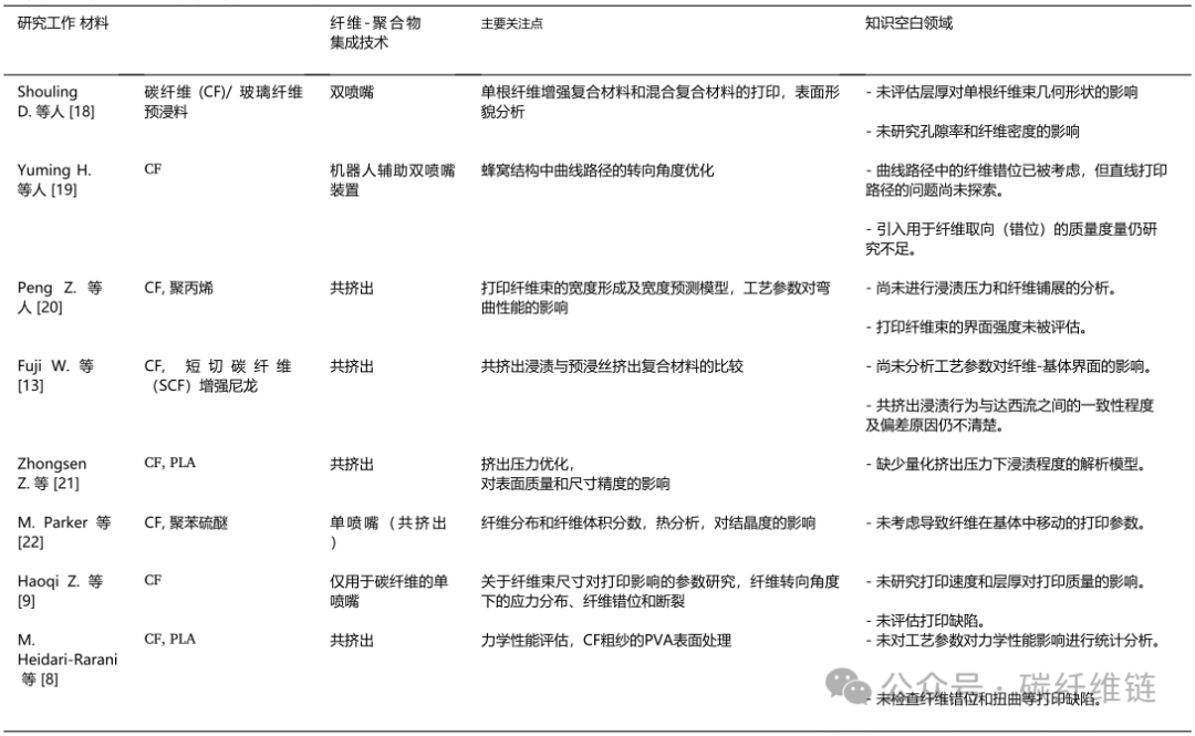
In recent years, there has been progress in evaluating fiber orientation effects in continuous fiber 3D printing, along with existing gaps in research.
**Abstract**
– This study optimizes single-bead deposition using the Taguchi method to explore the influencing factors of fiber misalignment, twisting, and interfacial characteristics in 3D printed continuous carbon fiber reinforced polymer composites (CCFRPCs);
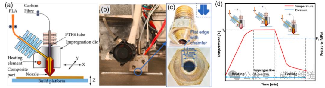
(a) Schematic of CFRP co-extrusion 3D printing, (b) self-developed print head, (c) nozzle used (1 mm opening, 1.2 mm middle ring, 1.4 mm outer ring), (d) representative schematic showing the history of impregnation temperature, where Ti is the impregnation temperature and Pi is the impregnation pressure inside the nozzle.
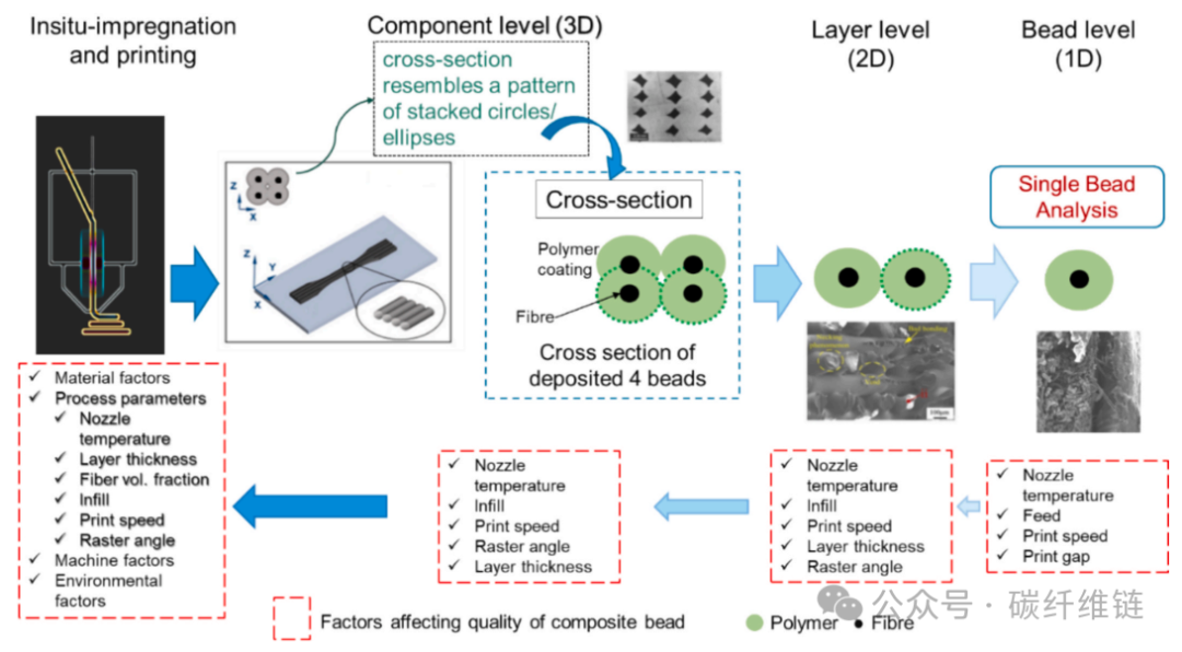
The classification of CFRP additive manufacturing printing: examining co-extrusion 3D printing at the component, layer, or bead level, considering the corresponding process parameters.
– A volume conservation-based predictive model is proposed to evaluate fiber misalignment level (FML), twisting level (FTL), and orientation efficiency factor (ηₒ), establishing a strong correlation with mechanical properties;
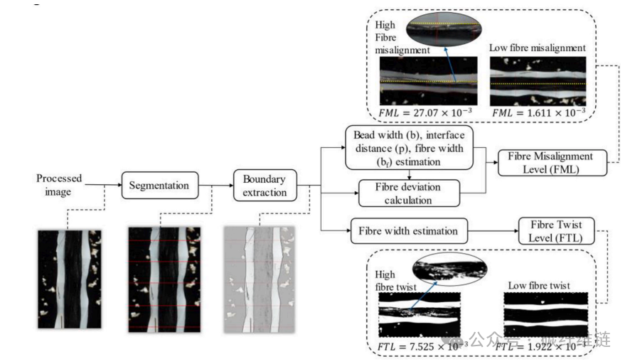
Calculation process and examples for FML and FTL.
– An innovative single-fiber pull-out test reveals three typical fiber morphologies—linear, hooked, and wavy—corresponding to different orientation efficiencies;
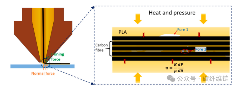
Schematic showing the process of PLA matrix impregnation into carbon fiber bundles.
– Experimental results show that samples with high orientation efficiency exhibit a 158% increase in interfacial bonding strength and a 378% increase in pull-out energy, with tensile strength doubling compared to previously reported fiber content.
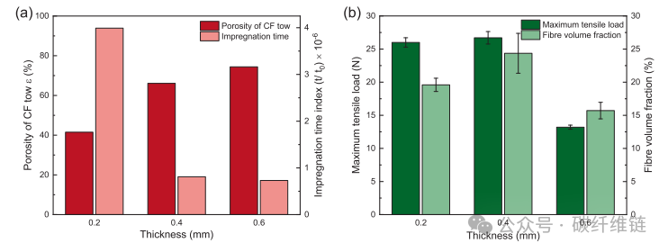
(a) Porosity calculated based on fiber bundle thickness and its theoretical impregnation time index, (b) maximum tensile load of printed samples versus fiber bundle thickness and corresponding fiber volume fraction.
**Methods**
– Co-extrusion 3D printing technology is employed, combining PLA matrix with continuous carbon fibers (CCF), conducting single-bead deposition experiments on self-developed equipment;
– A bead width prediction model based on the principle of volume conservation is established, considering the effects of nozzle movement speed, feed rate, and printing gap on bead formation;
– Two quantitative indicators, fiber misalignment level (FML) and fiber twisting level (FTL), are introduced, with data obtained through digital microscope image analysis;
– A fiber orientation efficiency factor (ηₒ) is proposed, integrating normalized values of FML and FTL to characterize fiber deposition quality;
– A Taguchi L9 orthogonal experimental design is used to analyze the effects of four parameters—nozzle temperature, printing speed, polymer feed rate, and printing gap—on FML and FTL, with S/N ratio and ANOVA determining the main control factors;
– A single-bead dual-side multi-fiber pull-out test is designed to evaluate interfacial bonding strength and pull-out energy under different fiber orientations;
– ASTM D3039 standard tensile samples are prepared to verify mechanical properties under optimized parameters, and the modified rule of mixtures (MRoM) is used in conjunction with ηₒ to predict composite strength and modulus.
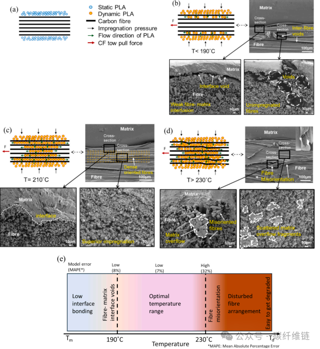
Schematic of the impregnation process and SEM micrographs at different printing temperatures. (a) Schematic of carbon fiber bundles and PLA, (b) impregnation schematic at T < 190 ◦C, (c) at T = 210 ◦C, and (d) at T > 230 ◦C. (e) The effect of printing paths on impregnation across different temperature ranges.
**Conclusion**:**
– This work significantly enhances the precision and quantifiability of fiber orientation control in 3D printed continuous carbon fiber composites, establishing a complete mapping framework from process parameters to fiber deposition quality to mechanical properties, promoting the customized manufacturing of high-performance structural components;
– Innovations: The first proposal of FML and FTL quantitative indicators and ηₒ efficiency factor, along with the innovative design of single-bead pull-out tests revealing the relationship between fiber morphology and interfacial behavior, fills the gap in bead-level fiber orientation analysis;
– Performance: Achieving a tensile strength of 203.93 MPa (30% fiber volume fraction), approximately 100% improvement over similar studies, with interfacial strength and pull-out energy increased by 158% and 378%, respectively, and MRoM predictions aligning well with experimental results;
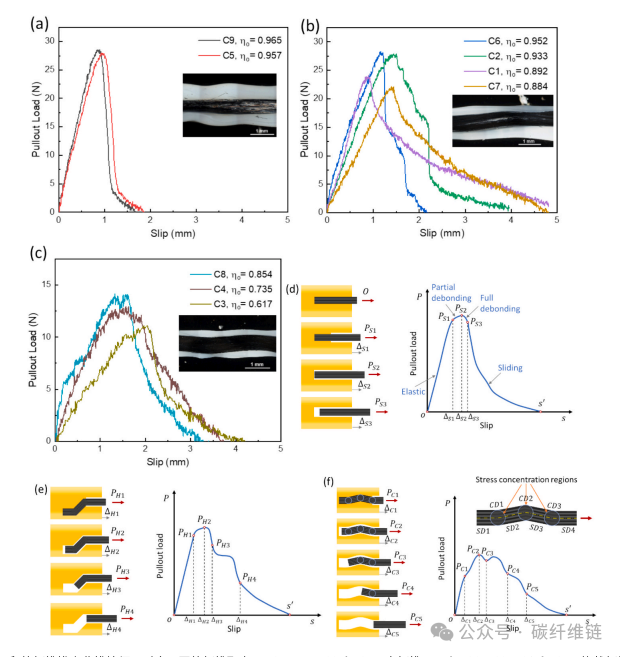
Characteristics of fiber pull-out curves under different conditions for single-bead printing, corresponding to different fiber orientations (ηO): (a) C9 and C5 (straight fibers), (b) C6, C2, C1, and C7 (hooked fibers), and (c) C8, C4, and C3 (wavy fibers); the embedded image shows fiber-matrix alignment. The corresponding pull-out load-slip curve schematic: (d) straight fibers, (e) hooked fibers, (f) wavy fibers; straight channel (SD) and curved channel (CD) represent the embedded structure of wavy carbon fibers. Key points include: O: starting point of fiber pull-out load, S: state of fiber detachment from the matrix, P: maximum pull-out load, Δ: fiber slip amount corresponding to load P. S: straight fibers, H: hooked fibers, C: wavy fibers.
Disclaimer|Some materials are sourced from publicly available information, and copyright belongs to the original authors.This platform publishes solely to convey a different perspective and does not represent endorsement or support of that perspective.If there are any copyright issues, please contact us for resolution.