Chapter 8
Writing Your Own Library – Building a Library Function Prototype
In fact, building a firmware library is a time-consuming and labor-intensive task, and it requires a certain level of familiarity with the chip from the developer. Even when a firmware library is highly encapsulated, reading and understanding the underlying code of that library can become quite challenging. The official FSP library used by Renesas RA series microcontrollers is an example of such a highly encapsulated firmware library. Fortunately, the purpose of the FSP library is to encapsulate the hardware layer for developers, so generally speaking, the FSP library is convenient; developers only need to learn how to use the FSP library without delving into its underlying details.
Typically, firmware libraries are built by chip manufacturers, such as the FSP library, which is constructed and maintained by Renesas. To help readers better understand the role of firmware libraries, we will next explain a method for building a lower-level encapsulated firmware library. It is important to note that the library function prototype constructed in this chapter is quite different from the actual FSP library, but it aims to assist readers in understanding and using the FSP library.
8.1
Hardware Design
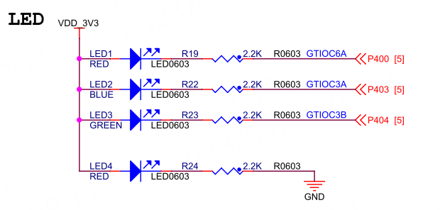
The LED circuit diagram for the Wildfire Qiming 6M5 development board is shown below.
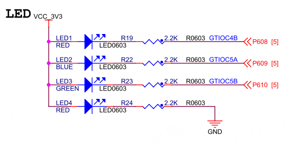
The LED circuit diagram for the Wildfire Qiming 4M2 development board is shown below.
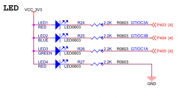
The LED circuit diagram for the Wildfire Qiming 2L1 development board is shown below.
8.2
Software Design
8.2.1
Creating a New Project
For the e2 studio development environment: Copy the previously created e2s project template“05_Template”, then rename the project folder to“09_Register_MyLib”, and finally import it into our e2 studio workspace.
For the Keil development environment: Copy the previously created Keil project template“06_Template”, then rename the project folder to“09_Register_MyLib”, and double-click the Keil project file inside that folder to open the project.
After the project is created, create a new folder named “ioport” under the “src” folder in the project root directory, and then enter the “ioport” folder to create the source file and header file for the ioport driver: “ra_ioport.c” and “ra_ioport.h”. The project file structure is as follows.
List 1: File Structure
Swipe left or right to view the complete content
09_Register_MyLib├─ ......└─ src ├─ ioport │ ├─ ra_ioport.c │ └─ ra_ioport.h └─ hal_entry.cWarning
Note: For users of the Keil development environment, after placing the code files in the “src” folder, the Keil software will not automatically add them to the project. You need to open the RASC FSP configuration interface, click the “Generate Project Content” button in the upper right corner once, so that the code files in the “src” folder will be automatically added to the project. Then close the FSP configuration interface and return to Keil, and after compiling once, a prompt box will appear indicating that the project structure has changed; click OK. Users of e2 studio do not need to do this.
8.2.2
Including Header Files with Register Definitions
In “ra_ioport.h”, include the header file“hal_data.h” to indirectly include the register definition header files:R7FA6M5BH.h or R7FA4M2AD.h or R7FA2L1AB.h.
List 2: Code Listing 8-1: ra_ioport.h
Swipe left or right to view the complete content
#include "hal_data.h" // Indirectly includes header files "R7FA6M5BH.h" / "R7FA4M2AD.h" / "R7FA2L1AB.h"8.2.3
Enumeration Type Definitions for Port and Pin Numbers
We need to define enumeration types for port and pin numbers to represent a specific pin to be controlled. However, defining enumeration types for port and pin numbers like: “BSP_IO_PORT_04_PIN_00”, “BSP_IO_PORT_04_PIN_03”, and “BSP_IO_PORT_04_PIN_04”
will cause conflicts with the enumeration definitions in the FSP library, so we temporarily separate the definitions for port and pin numbers.
List 3: Code Listing 8-2: ra_ioport.h File
Swipe left or right to view the complete content
/* IOPORT Port Definitions */typedef enum io_port {IO_PORT_00 = 0x0000, ///< IO port 0IO_PORT_01 = 0x0100, ///< IO port 1IO_PORT_02 = 0x0200, ///< IO port 2IO_PORT_03 = 0x0300, ///< IO port 3IO_PORT_04 = 0x0400, ///< IO port 4IO_PORT_05 = 0x0500, ///< IO port 5IO_PORT_06 = 0x0600, ///< IO port 6IO_PORT_07 = 0x0700, ///< IO port 7IO_PORT_08 = 0x0800, ///< IO port 8IO_PORT_09 = 0x0900, ///< IO port 9IO_PORT_10 = 0x0A00, ///< IO port 10IO_PORT_11 = 0x0B00, ///< IO port 11IO_PORT_12 = 0x0C00, ///< IO port 12IO_PORT_13 = 0x0D00, ///< IO port 13IO_PORT_14 = 0x0E00, ///< IO port 14} IO_Port_t;/* IOPORT Pin Definitions */typedef enum io_pin {IO_PIN_00 = 0x0000, ///< IO port 0 pin 0IO_PIN_01 = 0x0001, ///< IO port 0 pin 1IO_PIN_02 = 0x0002, ///< IO port 0 pin 2IO_PIN_03 = 0x0003, ///< IO port 0 pin 3IO_PIN_04 = 0x0004, ///< IO port 0 pin 4IO_PIN_05 = 0x0005, ///< IO port 0 pin 5IO_PIN_06 = 0x0006, ///< IO port 0 pin 6IO_PIN_07 = 0x0007, ///< IO port 0 pin 7IO_PIN_08 = 0x0008, ///< IO port 0 pin 8IO_PIN_09 = 0x0009, ///< IO port 0 pin 9IO_PIN_10 = 0x000A, ///< IO port 0 pin 10IO_PIN_11 = 0x000B, ///< IO port 0 pin 11IO_PIN_12 = 0x000C, ///< IO port 0 pin 12IO_PIN_13 = 0x000D, ///< IO port 0 pin 13IO_PIN_14 = 0x000E, ///< IO port 0 pin 14IO_PIN_15 = 0x000F, ///< IO port 0 pin 15} IO_Pin_t;8.2.4
Enumeration Type Definitions for IOPORT Related Functions
Next, we define enumeration types for IOPORT related functions, where each enumeration type corresponds to one of the IOPORT configuration functionalities.
List 4: Code Listing 8-3: ra_ioport.h File
Swipe left or right to view the complete content
/* IO Pin Modes */typedef enum {IO_MODE_GPIO = 0, /* General GPIO Function */IO_MODE_AF = 1, /* Multiplexed Function */IO_MODE_AN = 2 /* Analog Input/Output Function */} IO_Mode_t;/* IO Pin Directions */typedef enum {IO_DIR_INPUT = 0, // Pin used as GPIO input functionIO_DIR_OUTPUT = 1 // Pin used as GPIO output function} IO_Dir_t;/* IO Pin Output Types */typedef enum {IO_OTYPE_PP = 0x00, /* Push-Pull Mode */IO_OTYPE_OD = 0x01 /* Open-Drain Mode */} IO_OType_t;/* IO Pin Drive Capabilities */typedef enum {IO_DRIVE_LOW = 0, // Low driveIO_DRIVE_MIDDLE = 1, // Middle driveIO_DRIVE_HSHD = 2, // High-speed high-driveIO_DRIVE_HIGH = 3 // High drive} IO_DriveCapability_t;/* IO Pin Output Levels */typedef enum io_level {IO_LEVEL_LOW = 0, // LowIO_LEVEL_HIGH // High} IO_Level_t;/* IO Pin Pull-Up/Down */typedef enum {IO_NO_PULL = 0x00u, /* Floating Input */IO_PULL_UP = 0x01u, /* Pull-Up Input *///IO_PULL_DOWN = 0x02u /* RA6M5/RA4M2/RA2L1 pins do not have pull-down functionality */} IO_Pull_t;

Need Technical Support?
If you have any questions while using Renesas MCU/MPU products, you can scan the QR code below or copy the URL into your browser to access theRenesas Technical Forum for answers or online technical support.

https://community-ja.renesas.com/zh/forums-groups/mcu-mpu/
To Be Continued
Recommended Reading
Development Tools e2s/Keil/RASC User Guide – Renesas RA Series FSP Library Development Practical Guide (17)
The First Experiment: Lighting Up an LED with Registers – Renesas RA Series FSP Library Development Practical Guide (18)

Experiment: Lighting Up an LED Using Registers – Renesas RA Series FSP Library Development Practical Guide (19)