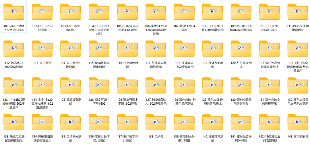
Follow the blue text, reply “Entry Materials” to get a comprehensive tutorial from beginner to advanced on microcontrollers
The development board will take you in, we will help you fly
Written by | Wujii (WeChat: 2777492857)

#include<reg52.h>    // Include header file, generally no need to modify, header file contains definitions of special function registers
sbit IR=P3^2;  // Infrared interface flag
#define DataPort P0 // Define data port, replace DataPort with P0 in the program

sbit LATCH1=P2^2;// Define latch enable port for segment latch
sbit LATCH2=P2^3;// Define latch for bits

/*------------------------------------------------                Global variable declaration------------------------------------------------*/
unsigned char code dofly_DuanMa[10]={0x3f,0x06,0x5b,0x4f,0x66,0x6d,0x7d,0x07,0x7f,0x6f}; // Display segment code values 0~9
unsigned char irtime; // Global variable for infrared
bit irpro_ok,irok;
unsigned char IRcord[4];
unsigned char irdata[33];

/*------------------------------------------------                  Function declaration------------------------------------------------*/
void Ir_work(void);
void Ircordpro(void);

/*------------------------------------------------                  Timer 0 interrupt handler------------------------------------------------*/
void tim0_isr (void) interrupt 1 using 1{  irtime++;  // Used to count the time between two falling edges}

/*------------------------------------------------                  External interrupt 0 handler------------------------------------------------*/
void EX0_ISR (void) interrupt 0 // External interrupt 0 service function{  static unsigned char  i;             // Receive infrared signal processing  static bit startflag;                // Whether to start processing flag
if(startflag)                         {    if(irtime<63&&irtime>=33) // Guide code TC9012 head code, 9ms + 4.5ms
    i=0;    irdata[i]=irtime; // Store the duration of each level for future judgment of 0 or 1
    irtime=0;    i++;    if(i==33)    {        irok=1;        i=0;    }
    }    else    {    irtime=0;    startflag=1;    }
}

/*------------------------------------------------                Timer 0 initialization------------------------------------------------*/
void TIM0init(void) // Timer 0 initialization{
  TMOD=0x02; // Timer 0 working mode 2, TH0 is reload value, TL0 is initial value
  TH0=0x00; // Reload value  TL0=0x00; // Initial value  ET0=1;    // Enable interrupt  TR0=1;    }

/*------------------------------------------------                  External interrupt 0 initialization------------------------------------------------*/
void EX0init(void){ IT0 = 1;   // Specify external interrupt 0 triggered by falling edge, INT0 (P3.2) EX0 = 1;   // Enable external interrupt EA = 1;    // Enable global interrupt}

/*------------------------------------------------                  Key value processing------------------------------------------------*/
void Ir_work(void) // Infrared key value scatter program{   switch(IRcord[2]) // Judge the third digital value   {         case 0:DataPort=dofly_DuanMa[1];break; // 1 display corresponding key value         case 1:DataPort=dofly_DuanMa[2];break; // 2         case 2:DataPort=dofly_DuanMa[3];break; // 3         case 3:DataPort=dofly_DuanMa[4];break; // 4         case 4:DataPort=dofly_DuanMa[5];break; // 5         case 5:DataPort=dofly_DuanMa[6];break; // 6         case 6:DataPort=dofly_DuanMa[7];break; // 7         case 7:DataPort=dofly_DuanMa[8];break; // 8         case 8:DataPort=dofly_DuanMa[9];break; // 9        default:break;    }       irpro_ok=0; // Processing complete flag
  }

/*------------------------------------------------                Infrared code value processing------------------------------------------------*/
void Ircordpro(void) // Infrared code value processing function{   unsigned char i, j, k;  unsigned char cord,value;
  k=1;  for(i=0;i<4;i++)      // Process 4 bytes     {      for(j=1;j<=8;j++) // Process 1 byte 8 bits         {          cord=irdata[k];          if(cord>7) // Greater than a certain value is 1, this has an absolute relationship with the crystal oscillator, here using 12M calculation, this value can have a certain error             value|=0x80;          if(j<8)                    {                         value>>=1;                        }           k++;         }     IRcord[i]=value;     value=0;          }          irpro_ok=1; // Processing completed flag set to 1}

/*------------------------------------------------                    Main function------------------------------------------------*/
void main(void){ EX0init(); // Initialize external interrupt TIM0init();// Initialize timer
  DataPort=0xfe; // Get bit code, the first digital tube is selected, that is, binary 1111 1110  LATCH2=1;      // Bit latch  LATCH2=0;
 while(1) // Main loop   {    if(irok)                        // If received well, proceed with infrared processing          {              Ircordpro();            irok=0;          }
if(irpro_ok) // If processed well, proceed with work processing, such as displaying corresponding numbers after pressing the corresponding key { Ir_work(); } }}#include <reg52.h> #define uchar unsigned char#define uint unsigned int sbit KEY1 = P3^2; // Stepper motor clockwise rotation
sbit KEY2 = P3^3; // Stepper motor counterclockwise rotation
sbit KEY3 = P3^4; // Stepper motor speed control
uchar Step = 0;bit FB_flag = 0;
unsigned char code F_Rotation[8]={0x08,0x18,0x10,0x30,0x20,0x60,0x40,0x48}; // Clockwise rotation table
unsigned char code B_Rotation[8]={0x48,0x40,0x60,0x20,0x30,0x10,0x18,0x08}; // Counterclockwise rotation table
/********************************************************************* Name : Delay_1ms()* Function : Delay subroutine, delay time is 1ms * x* Input : x (number of milliseconds to delay)* Output : None***********************************************************************/
void Delay(uint i){ uchar x,j; for(j=0;j<i;j++) for(x=0;x<=148;x++); }
void KEY(void){ if(KEY1 == 0) // Press P3.2 to achieve clockwise rotation of the stepper motor { Delay(15); if(KEY1 == 0) { FB_flag = 0; } Delay(200); } if(KEY2 == 0) // Press P3.3 to achieve counterclockwise rotation of the stepper motor { Delay(15); if(KEY2 == 0) { FB_flag = 1; } Delay(200); } if(KEY3 == 0) // Press P3.4 to achieve speed control of the stepper motor { Delay(15); if(KEY3 == 0) { Step++; if(Step == 3) { Step = 0; } } Delay(200); }}
void main(){ uchar i; // uint k = 0; while(1) { KEY(); // Key processing function for(i=0;i<8;i++) // Because there are 8 control timing { // k++; // if(k == 4096) while(1); if(FB_flag == 0) { P1 = F_Rotation[i]; // Rotate clockwise } else { P1 = B_Rotation[i]; // Rotate counterclockwise } Delay(1+Step); // Changing this parameter can adjust the motor speed } }}end

Here are more original content from Wujii about personal growth experiences, industry experience, and technical insights.
1.What is the growth path of an electronics engineer? 10 years 5000 words summary
2.How to quickly understand others’ code and thinking
3.How to manage too many global variables in microcontroller development projects?
4.Why do most microcontroller programs in C language use global variables??
5.How to achieve modular programming in microcontrollers? The practicality is astonishing!
6.Detailed explanation of callback function usage and actual effects in C language
7.Step-by-step guide to C language queue implementation code, easy to understand and super detailed!
8.Detailed explanation of pointer usage in C language, easy to understand and super detailed!