
Click “Read the original text” to access more VxWorks resources
VxWorks technical materials are available for free download; resources are sourced from the internet, and copyright belongs to the original authors!
6.1 Introduction to USB Specifications
6.1.1 Overview
This chapter does not intend to describe the contents of the USB specifications in too much detail; it merely provides a general description of some USB specifications so that readers do not find it too abrupt during the subsequent software analysis process. However, if one wants to conduct a clear software analysis, it is necessary to carefully read the relevant USB specifications.
USB is a high-speed serial transmission bus that supports hot swapping. It uses differential signaling to transmit data, with a maximum speed of up to 480Mb/S. USB 2.0 is designed to be backward compatible, allowing full-speed (USB 1.1) or low-speed (USB 1.0) devices to connect to a high-speed (USB 2.0) host, with the host supporting them through separated transmissions.
A USB HOST can support up to 128 addresses simultaneously, with address 0 being the default address used only temporarily during device enumeration and cannot be assigned to any device. Therefore, a USB HOST can support a maximum of 127 addresses simultaneously. If a device occupies only one address, then a maximum of 127 USB devices can be supported. In practice, if 127 USB devices are to be connected, a USB HUB must be used, and the USB HUB also occupies an address, so the actual number of USB functional devices that can be supported will be less than 127.
USB uses a polling broadcast mechanism to transmit data, where all transmissions are initiated by the host. At any given time, only one data packet is allowed to be transmitted within the entire USB system, meaning that the data packets seen on different physical transmission lines are the same broadcast data packets. USB employs a transmission mechanism of “token packet” – “data packet” – “handshake packet”, specifying the destination or source device address and endpoint in the token packet to ensure that only one device responds to the broadcast data/token packet. The handshake packet indicates whether the transmission was successful.
A pipe is a model for data transmission between the host and device endpoints, with two types of pipes: unformatted stream pipes and formatted message pipes. Any USB device has an information pipe once powered on, which is the default control pipe. The USB host uses this pipe to obtain the device’s description, configuration, status, and configure the device.
When a USB device connects to the HOST, the HOST must enumerate it through the default control pipe, completing operations such as obtaining its device description, allocating an address, obtaining its configuration description, and configuring it to be used normally. The plug-and-play feature of USB devices relies on this.
The USB system defines four types of transfers, which are:
-
Control transfer: mainly used for enumerating devices when connected and other specific operations related to the device.
-
Interrupt transfer: used for reliable transmission of small amounts of data with strict latency requirements, such as keyboards and game controllers.
-
Bulk transfer: used for reliable transmission of large amounts of data with relaxed latency requirements, such as USB flash drives.
-
Isochronous transfer: used for real-time data transmission with low reliability requirements, such as cameras and USB speakers.
Note: Interrupt transfer does not mean that the device will first interrupt the HOST and then notify the HOST to start transmission. Interrupt transfer is also initiated by the HOST, which polls the device to check if there is data to send; if so, it transmits the data; otherwise, it sends a NAK to the host.
USB devices communicate with the HOST through pipes, processing the following three types of requests on the default control pipe:
-
1. Standard requests: There are a total of 11 standard requests, such as obtaining device descriptions, setting addresses, obtaining configuration descriptions, etc. All USB devices should support these requests. The HOST uses standard requests to identify and configure devices.
-
2. Class requests: USB also defines several subclasses, such as HUB class, mass storage class, etc. Different classes define several class requests, and devices should support the requests of their respective classes.
-
3. Vendor requests: This part of the requests is not defined by the USB specification but is defined by the device manufacturer for specific functionalities.
USB HUB provides a low-cost, low-complexity method for USB interface expansion. The HUB’s upstream PORT faces the HOST, while the downstream PORT faces devices (HUB or functional devices). On the downstream PORT, the HUB provides the capability to detect device connections and removals and powers each downstream PORT. The HUB can independently enable each downstream PORT, and different PORTs can operate at different speed levels (high-speed/full-speed/low-speed).
The USB HOST is responsible for detecting device connections/removals, managing control and data flows between the HOST and devices, collecting transmission status, and supplying bus power within the USB system.
6.1.2 USB Data Flow Model
The USB system adopts a layered structure for implementation, as shown in Figure 6.1:
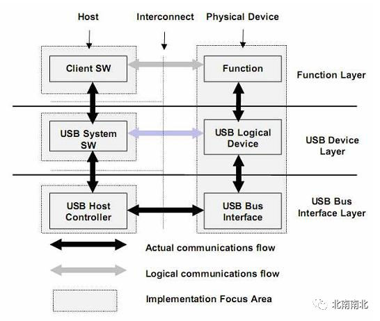
At the HOST side, application software (Client SW) cannot directly access the USB bus but must do so through USB system software and the USB host controller to communicate with USB devices on the USB bus. This structure can be logically divided into three levels: functional layer, device layer, and bus interface layer. The functional layer completes the functional description, definition, and behavior; the device layer completes the conversion from functional level to transmission level, turning a functional behavior into a series of basic transmissions; the USB bus interface layer handles the bit stream on the bus, completing the physical layer implementation of data transmission and bus management. The black arrows in the figure represent actual data flows, while the gray arrows represent logical communications.
Physically, USB devices are connected to the HOST through a layered star bus, but logically, the HUB is transparent, with each USB device directly connected to the HOST, forming a one-to-one relationship with the application software on the HOST, as shown in Figure 6.2:
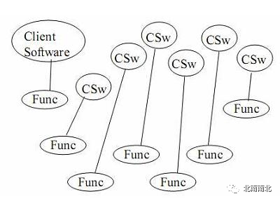
The communication between each application software and functional devices is independent. Application software initiates IRQ requests through the USB device driver (USBD) to request data transmission. The host controller driver (HCD) receives the IRQ requests, parses them into USB transfers and transfer transactions, and schedules all transfer transactions within the USB system (since multiple application software may initiate IRQ requests simultaneously). The host controller executes the scheduled transfer tasks, transmitting data packets over the shared USB bus.
In the USB system, data transmission is generally seen as occurring between the HOST and USB functional devices; microscopically, it occurs between the application software’s buffer and the USB functional device’s endpoints. Generally, endpoints have buffers, and USB communication can be viewed as data exchange between the application software buffer and the device endpoint buffer, with the exchange channel referred to as a pipe. Multiple pipes are usually needed to complete data exchange because the same pipe only supports one type of data transmission. Several pipes used together to control the device are referred to as the device’s interface, which illustrates the relationship between endpoint pipes and interfaces.
6.1.3 USB Protocol Layer Specifications
All USB packets start with a SYNC. The SYNC width for high-speed packets is 32 bits, while for full-speed/low-speed packets, it is 8 bits. The actual received SYNC width may be less than this value due to USB HUB interference.
The format of USB data packets is shown in Table 6.1.
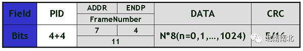
In which PID represents the type of data packet, divided into four categories: token, data, handshake, and special packets, with a total of 16 types of PID. Specific definitions of data packet types can be referenced in the USB specifications.
For token packets, the PID is followed by a 7-bit address and a 4-bit endpoint number. Token packets do not have a data field and end with a 5-bit CRC checksum. SOF is a special type of token packet, with the PID followed by an 11-bit frame number.
For data packets, the PID is followed directly by the data field, with the length of the data field being N bytes, and the data field ends with a 16-bit CRC checksum.
Handshake packets only have a PID field, with no data or checksum.
Data transmission on the USB bus occurs in packets, and packets can only be transmitted within frames. The frame cycle for high-speed USB buses is 125μS, while for full-speed and low-speed USB buses, it is 1ms. The start of a frame is indicated by a specific packet (SOF packet), and the end of a frame is indicated by EOF. EOF is not a packet but a state of voltage level, during which no data transmission is allowed.
6.1.4 Transaction Transfer (Transaction) Process
The transaction transfer process of USB varies depending on the transfer type.
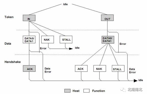
1. Bulk Transfer
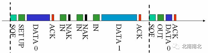
Figure 6.3 illustrates a box representing a packet, where gray packets represent those sent by the host, and white packets represent those sent by the device. Bulk transfer is reliable and requires handshake packets to indicate the result of the transmission. If the data volume is large, multiple bulk transaction transfers will be used to complete the transfer of all data, and during the transmission process, the PID of the data packets will alternate between DATA0-DATA1-DATA0-… to ensure synchronization between the sender and receiver.
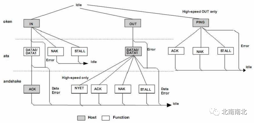
A bulk transfer consists of one or more bulk transaction transfers.
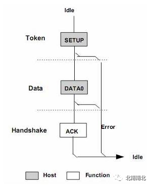
2. Control Transfer
A control transfer is divided into three (or two) phases: setup, data (which may be absent), and status. Each phase consists of one or more (data phase) transaction transfers.
Figure 6.4 shows the transaction transfer process during the setup phase. It can be seen that there is not much difference in the process compared to bulk transfer; the only differences are in the endpoints where the transaction transfer occurs, the maximum packet length supported, priority, and other transparent factors for the user.
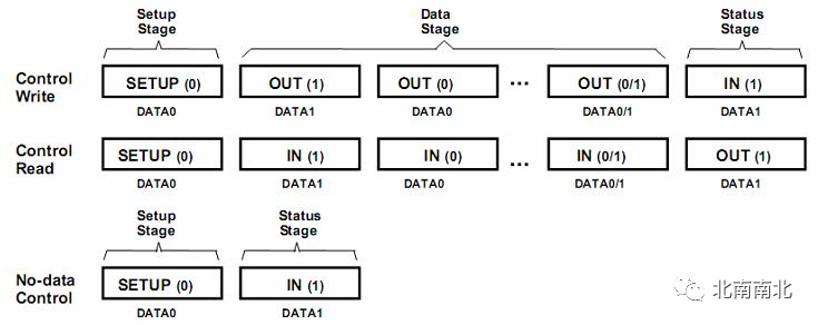
After the setup phase, there may be a data phase, which will be completed through one or more control transfer transactions. The PID flipping mechanism will also be used. During the setup phase, the device can only return an ACK packet or no packet at all.
Finally, the status phase indicates the success or failure of the transmission through a control transaction transfer in the opposite direction to the previous one. If successful, a data packet of length 0 will be returned; otherwise, a NAK or STALL will be returned. Figure 6.5 illustrates the data packet for the entire control transfer:
3. Interrupt Transfer
Interrupt transfer has similar differences to bulk transfer, only differing in the endpoints where transaction transfers occur, the maximum packet length supported, priority, etc.
When scheduling interrupt transfer tasks, the host initiates interrupt transfers based on the polling interval specified in the corresponding interrupt endpoint descriptor. Interrupt transfers have a higher priority, second only to isochronous transfers.
Similarly, interrupt transfers also use the PID flipping mechanism to ensure synchronization of data between sender and receiver. Figure 6.6 illustrates the flowchart for interrupt transaction transfers.
4. Isochronous Transfer
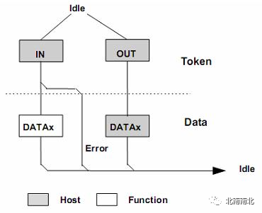
Isochronous transfer is an unreliable transfer, so it does not have handshake packets and does not support PID flipping. When scheduling transaction transfers, isochronous transfers have the highest priority.
Figure 6.8 shows the data timing diagram for isochronous transfer on the USB bus.
Packets are the smallest unit of data transmission on the USB bus and cannot be interrupted or interfered with; otherwise, errors will occur. Several data packets make up a transaction transfer, and a transaction transfer cannot be interrupted; the packets belonging to a transaction transfer must be consecutive and cannot span frames.
A transmission consists of one to multiple transaction transfers and can span frames.
This section mainly introduces the basic principles of USB. This article primarily references the USB 2.0 specification translated by Hevry, and more detailed information can be found in the USB 2.0 specification.
6.2 Software Structure of USB Drivers
6.2.1 Overview
As shown in Figure 6.9, the connection of USB devices in a computer system is illustrated.
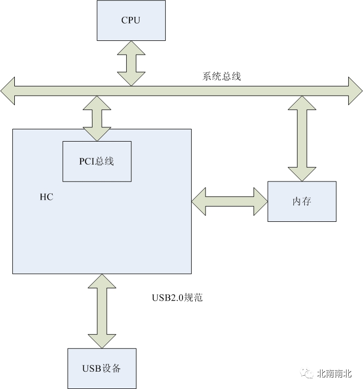
This is somewhat similar to network interfaces. Functionally, the primary role of a network interface is data transmission, while the primary role of a USB interface is to control the data transmission devices, and there are certain similarities between the two.
From a hardware perspective, the USB control device HC can be viewed as a PCI device, allowing the computer system to communicate with external USB devices through this PCI device. This is similar to the function of a network card. Figure 6.10 compares the USB driver with the network card driver; structurally, the network card and HC serve the same purpose, acting as an interface converter.
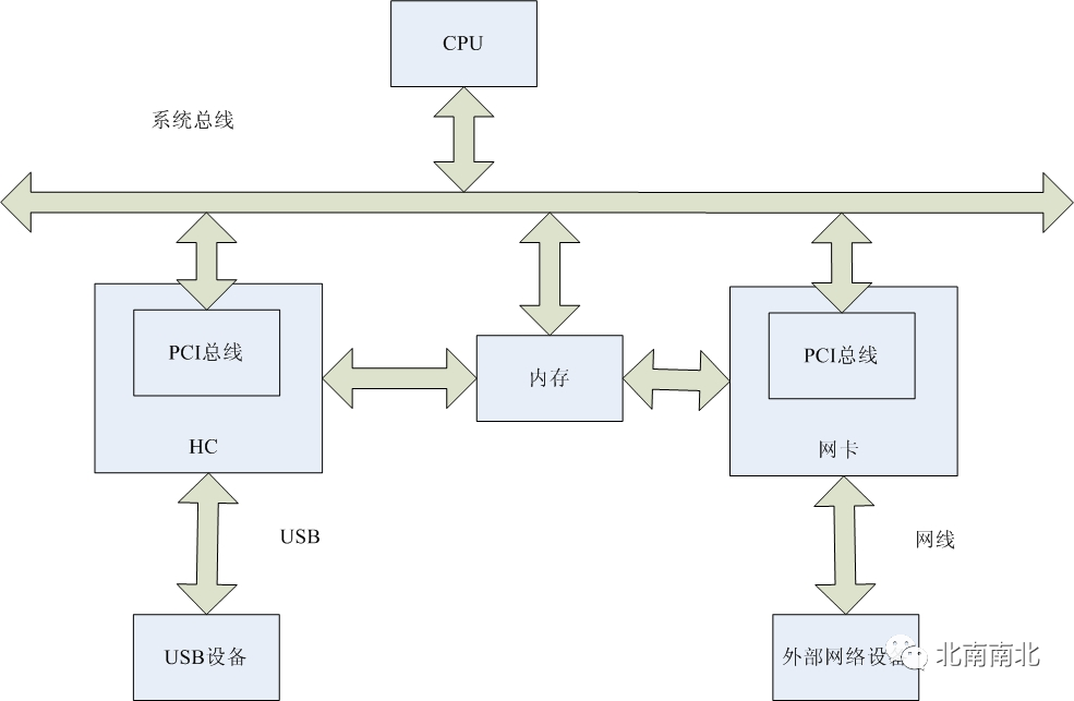
The hardware structural similarities between the two also result in software structural similarities. Table 6.2 lists the comparison between the structural hierarchy of networks and the hierarchy of USB device drivers:

The software structural similarities also dictate that USB driver software is layered, consisting of device driver layer, USBD layer, and HCD layer, as shown in Figure 6.11.
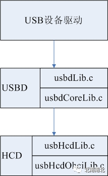
The upper layer calls lower-level functions through standard function interfaces to complete corresponding functions, while lower-level functions, upon receiving data, call the callback functions registered by the upper layer to pass the received data to the upper layer. Specifically, this is primarily reflected in the following aspects:
-
l The USBD layer implements a general interface function library usbdLib, allowing the application layer to interact with the USB device’s corresponding layer through the function library usbdLib;
-
l The HCD layer implements a general interface function library usbHcdLib, and the USBD layer interacts with the USB device’s corresponding layer through the general interface function library;
-
l The public callback function interface reserved for the upper layer in the USBD layer is pIrp->userCallback. For control pipes, the USBD layer also reserves an additional callback function interface for the upper layer, pUrb->callback;
-
l The callback function interface reserved for the USBD layer in the HCD layer is pIrp->usbdCallback.
For a USB device, only data signals and control signals can be transmitted on the USB bus, and interrupt signals cannot be provided because the USB bus is not connected to the computer system’s PIC. However, for HC, there are strict interrupt signals, and the interrupt signal line is connected to the PCI through the PCI interface. The HC’s interrupt handling function is intHandler, which is responsible for sending a semaphore pHost->intPending to the task intThread. After receiving the semaphore, intThread performs the specific interrupt handling, making the interrupt handling program simple and fast in execution, while the resource-consuming part is left to the system task, greatly improving the interrupt response speed.
6.2.2 Function Library usbdLib
The USBD layer is an abstraction layer, as shown in the USB specifications; the USBD layer abstracts USB devices as nodes, thus turning the interaction between the system and USB devices into an interaction between clients and USB nodes. The implementation of the USBD layer can be divided into two sub-layers: the interface sub-layer and the implementation sub-layer. The interface sub-layer provides a series of general interfaces for the upper layer, mainly completed by the function library usbdLib; the implementation sub-layer implements the functionality of the general interface functions, primarily realized by the function library usbdCoreLib.
In fact, the function library usbdCoreLib layer has already implemented a general interface function urbExecBlock; however, this interface function is too complex and not conducive to upper-layer calls, so usbdLib implements a series of general interfaces by calling the function urbExecBlock, thus isolating the application layer from the usbd layer.
This function library is relatively simple, and a brief description is as follows.
1. LOCAL VOID urbInit
    (
pURB_HEADER pUrb,

    USBD_CLIENT_HANDLE clientHandle,

    UINT16 function,

    URB_CALLBACK callback,

    pVOID userPtr,

    UINT16 totalLen
)
This function initializes a URB structure using parameters. The URB structure will be used as parameters for the general interface function.
The parameters of the urbInit function include:
-
clientHandle: indicates a client;
-
function: the function to be completed;
-
callback: called when the URB finishes;
-
userPtr: user-specified pointer;
-
totalLen: length of the URB structure, usually sizeof(USBD_URB)
2. LOCAL VOID urbCallback
    (
pVOID pUrb
)
This function is designated by the urbExecBlock() function as the callback function for the URB structure, called by the function usbdCoreEntry before it ends for synchronization.
3. LOCAL STATUS urbExecBlock
    (
pURB_HEADER pUrb
)
This function is the core of the usbdLib function library. It is responsible for initializing the parameter pUrb and calling the function usbdCoreEntry for lower-level processing with this parameter.
There are several points to note about this function:
-
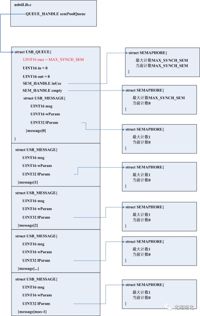
l The semaphore queue semPoolQueue is a FIFO queue, and only by retrieving a msg from the FIFO queue can the usbdCoreEntry function be called. After the call, the semaphore is returned to the FIFO, ensuring that the number of tasks executing the usbdCoreEntry function in the system does not exceed MAX_SYNCH_SEM (see the function usbdInitialize).
-
l Each element in the queue is a semaphore; what is the purpose of this semaphore? From the code perspective, it is merely to ensure the completion of URB execution. Since the function urbExecBlock directly calls the function usbdCoreEntry, this must occur in the same task, and there is no situation where the function has not finished executing after being called. Personally, I feel this functionality is unnecessary.
-
l In the code, we see that if usbdCoreEntry (pUrb) != OK, it cannot determine whether the function usbdCoreEntry called the function OSS_SEM_GIVE ((SEM_HANDLE) ((pURB_HEADER) pUrb)->userPtr), so the function OSS_SEM_TAKE ((SEM_HANDLE) msg.lParam, OSS_DONT_BLOCK) must be called to ensure that the semaphore is restored to its original state before returning it (note that the last parameter OSS_DONT_BLOCK differs from the parameter OSS_BLOCK called when usbdCoreEntry executes successfully).
4. STATUS usbdInitialize (void)
Initializes the usbdLib function library.
The initialization process includes:
-
l Creating the queue semPoolQueue (as shown);
-
l Calling urbInit (&urb.header, NULL, USBD_FNC_INITIALIZE, NULL, NULL,sizeof (urb)) and urbExecBlock (&urb.header) to complete the initialization of usbdCoreLib.
5. STATUS usbdShutdown (void)
The reverse process of the usbdInitialize function. First, it closes the usbdCoreLib layer, then releases the semaphore queue space allocated by the initialization function, and finally closes the OSS function library.
Note: When releasing the semaphore queue semPoolQueue, a semaphore must be obtained first before deleting it; all semaphores must be deleted before the USB_QUEUE structure pointed to by semPoolQueue can be deleted. The condition usbQueueGet (semPoolQueue, &msg, SYNCH_SEM_TIMEOUT) == OK can easily lead to memory leaks.
6. STATUS usbdClientRegister
    (
pCHAR pClientName,

    pUSBD_CLIENT_HANDLE pClientHandle
)
Calls the urbExecBlock function (parameter USBD_FNC_CLIENT_REG) to generate a USBD_CLIENT structure based on the provided pClientName and returns the handle of that structure.
7. STATUS usbdClientUnregister
    (
    USBD_CLIENT_HANDLE clientHandle
)
Calls urbExecBlock (parameter USBD_FNC_CLIENT_UNREG) to delete a USBD_CLIENT structure specified by clientHandle.
8. STATUS usbdMngmtCallbackSet
    (
    USBD_CLIENT_HANDLE clientHandle,

    USBD_MNGMT_CALLBACK mngmtCallback

    pVOID mngmtCallbackParam
)
Sets a management callback function for a client.
The management callback function provides a means for USBD to notify clients of asynchronous management events on the USB. For example, if a USB device issues a RESUME signal while the USB is in SUSPEND state, this event will be notified to the client through the management callback function.
9. STATUS usbdBusStateSet
    (
    USBD_CLIENT_HANDLE clientHandle,

    USBD_NODE_ID nodeId,

    UINT16 busState
    )
This function allows a client to set the state of the bus (SUSPEND/RESUME), with the bus specified by the parameter node (pNode->pBus).
When setting a bus to SUSPEND state, it is important to note that USBD will not automatically restore the bus to RESUME state; to restore it to RESUME state, this function must be called again (using the RESUME parameter). This is important for the USB “remote wakeup” feature, which allows a remote device to drive the RESUME signal on the bus. The client monitors this signal through the management callback and calls the usbdBusStateSet function to complete the operation.
Similarly, this function is also called via urbExecBlock (in fact, it is usbdCoreLib).
Note: Clients must use this function carefully, as it affects all USB devices on a bus, thereby impacting communication with all clients related to those devices.
10. STATUS usbdBusCountGet
    (
    USBD_CLIENT_HANDLE clientHandle,

    pUINT16 pBusCount
    )
This function retrieves the number of USB host controllers linked to the system. According to USB specifications, each host controller has its own root hub.
The number of HC in the system is not fixed and can be modified through the usbdHcdAttach() and usbdHcdDetach() functions.
11. STATUS usbdRootNodeIdGet
    (
    USBD_CLIENT_HANDLE clientHandle,

    UINT16 busIndex,

    pUSBD_NODE_ID pRootId
    )
This function is used to find the nodeID corresponding to a HC’s root hub. busIndex refers to the index of the USBD_HCD structure on the hcdList chain.
12. STATUS usbdHubPortCountGet
    (
    USBD_CLIENT_HANDLE clientHandle,

    USBD_NODE_ID hubId,

    pUINT16 pPortCount
    )
This function calls the usbdCoreLib’s fncHubPortCountGet function via the urbExecBlock interface. It retrieves the number of ports for a hub device.
13. STATUS usbdNodeIdGet
    (
    USBD_CLIENT_HANDLE clientHandle,

    USBD_NODE_ID hubId,

    UINT16 portIndex,

    pUINT16 pNodeType,

    pUSBD_NODE_ID pNodeId
    )
Retrieves the nodeId of the device connected to a specified port of a hub.
14. STATUS usbdNodeInfoGet
    (
    USBD_CLIENT_HANDLE clientHandle,

    USBD_NODE_ID nodeId,

    pUSBD_NODE_INFO pNodeInfo,

    UINT16 infoLen
    )
Retrieves information about a node. This information is stored in the nodeInfo element of the USBD_NODE structure.
15. STATUS usbdDynamicAttachRegister
    (
    USBD_CLIENT_HANDLE clientHandle,

    UINT16 deviceClass,

    UINT16 deviceSubClass,

    UINT16 deviceProtocol,

    USBD_ATTACH_CALLBACK attachCallback
    )
This function is called by the client to notify USBD that when USBD discovers a device of deviceClass/deviceSubClass/deviceProtocol, it should notify the client.
16. STATUS usbdDynamicAttachUnRegister
    (
    USBD_CLIENT_HANDLE clientHandle,

    UINT16 deviceClass,

    UINT16 deviceSubClass,

    UINT16 deviceProtocol,

    USBD_ATTACH_CALLBACK attachCallback
    )
Notifies USBD not to notify the client when devices of deviceClass/deviceSubClass/deviceProtocol are plugged or unplugged.
17. STATUS usbdFeatureClear
    (
    USBD_CLIENT_HANDLE clientHandle,

    USBD_NODE_ID nodeId,

    UINT16 requestType,

    UINT16 feature,

    UINT16 index
    )
Clears a USB feature.
18. STATUS usbdFeatureSet
    (
    USBD_CLIENT_HANDLE clientHandle,

    USBD_NODE_ID nodeId,

    UINT16 requestType,

    UINT16 feature,

    UINT16 index
    )
Sets a USB feature.
19. STATUS usbdConfigurationGet
    (
    USBD_CLIENT_HANDLE clientHandle,

    USBD_NODE_ID nodeId,

    pUINT16 pConfiguration
    )
Retrieves the configuration information of a USB device, which is stored at the address of pConfiguration.
20. STATUS usbdConfigurationSet
    (
    USBD_CLIENT_HANDLE clientHandle, /* Client handle */

    USBD_NODE_ID nodeId, /* Node Id of device/hub */

    UINT16 configuration, /* New configuration to be set */

    UINT16 maxPower /* max power this config will draw */
    )
Sets the configuration information of a USB device.
21. STATUS usbdDescriptorGet
    (
    USBD_CLIENT_HANDLE clientHandle,

    USBD_NODE_ID nodeId,

    UINT8 requestType,

    UINT8 descriptorType,

    UINT8 descriptorIndex,

    UINT16 languageId,

    UINT16 bfrLen,

    pUINT8 pBfr,

    pUINT16 pActLen
    )
Retrieves the descriptor information of a USB device (nodeId).
22. STATUS usbdDescriptorSet
    (
    USBD_CLIENT_HANDLE clientHandle,

    USBD_NODE_ID nodeId,

    UINT8 requestType,

    UINT8 descriptorType,

    UINT8 descriptorIndex,

    UINT16 languageId,

    UINT16 bfrLen,

    pUINT8 pBfr
    )
Sets the descriptor information of a USB device.
23. STATUS usbdInterfaceGet
    (
    USBD_CLIENT_HANDLE clientHandle,

    USBD_NODE_ID nodeId,

    UINT16 interfaceIndex,

    pUINT16 pAlternateSetting
    )
Retrieves the interface information of a USB device.
24. STATUS usbdInterfaceSet
    (
    USBD_CLIENT_HANDLE clientHandle,

    USBD_NODE_ID nodeId,

    UINT16 interfaceIndex,

    UINT16 alternateSetting
    )
Sets the interface information of a USB device.
25. STATUS usbdStatusGet
    (
    USBD_CLIENT_HANDLE clientHandle,

    USBD_NODE_ID nodeId,

    UINT16 requestType,

    UINT16 index,

    UINT16 bfrLen,

    pUINT8 pBfr,

    pUINT16 pActLen
    )
Queries the status of a USB device.
26. STATUS usbdAddressGet
    (
    USBD_CLIENT_HANDLE clientHandle,

    USBD_NODE_ID nodeId,

    pUINT16 pDeviceAddress
    )
Retrieves the address of a device.
27. STATUS usbdAddressSet
    (
    USBD_CLIENT_HANDLE clientHandle,

    USBD_NODE_ID nodeId,

    UINT16 deviceAddress
    )
Sets the address of a USB device.
28. STATUS usbdVendorSpecific
    (
    USBD_CLIENT_HANDLE clientHandle,

    USBD_NODE_ID nodeId,

    UINT8 requestType,

    UINT8 request,

    UINT16 value,

    UINT16 index,

    UINT16 length,

    pUINT8 pBfr,

    pUINT16 pActLen
)
This function allows the device to issue device-specific USB requests.
Specific USB devices may have special USB requests that cannot be accomplished with standard USB functionalities, thus requiring a function to send requests directly to the control pipe of the USB device.
29. STATUS usbdPipeCreate
    (
    USBD_CLIENT_HANDLE clientHandle,

    USBD_NODE_ID nodeId,

    UINT16 endpoint,

    UINT16 configuration,

    UINT16 interface,

    UINT16 transferType,

    UINT16 direction,

    UINT16 maxPayload,

    UINT32 bandwidth,

    UINT16 serviceInterval,

    pUSBD_PIPE_HANDLE pPipeHandle
    )
Creates a USBD_PIPE.
-
nodeId: specifies the device
-
endpoint: specifies the endpoint of the device, and the pipe is established between the client and an endpoint of the device. Configuration and interface specify the device’s configuration and interface.
-
transferType: transfer type: control and BULK
-
direction: specifies the direction of pipe transmission: IN/OUT/INOUT. The direction characteristic of a pipe does not change. INOUT is only used for control Pipe.
-
maxPayload: the maximum payload supported by the endpoint. This value is usually indicated in the device’s configuration descriptor, so this parameter is passed as an argument only after USBD has read the configuration descriptor from the USB device.
-
bandwidth: for control and bulk pipes, bandwidth is 0; for interrupt pipes, this value is the number of bytes to be transmitted per frame; for isochronous pipes, bandwidth refers to the number of bytes transmitted per second.
-
serviceInterval: only applicable to interrupt transfer pipes, indicating the maximum latency of the pipe (in milliseconds). If a device’s serviceInterval value is 20, it means that the device needs to be serviced every 20 milliseconds.
-
pPipeHandle: handle of the created PIPE.
30. STATUS usbdPipeDestroy
    (
    USBD_CLIENT_HANDLE clientHandle,

    USBD_PIPE_HANDLE pipeHandle
    )
Destroys a USB transfer pipe.
31. STATUS usbdTransfer
    (
    USBD_CLIENT_HANDLE clientHandle, /* Client handle */

    USBD_PIPE_HANDLE pipeHandle, /* Pipe handle */

    pUSB_IRP pIrp /* ptr to I/O request packet */
    )
The client uses this function to initiate a transfer on a specified pipe. The transfer is described by an IRP structure or an I/O request packet, which must be allocated and initialized before calling the usbdTransfer() function.
32. STATUS usbdTransferAbort
    (
    USBD_CLIENT_HANDLE clientHandle,

    USBD_PIPE_HANDLE pipeHandle,

    pUSB_IRP pIrp
    )
Terminates a USB transfer.
33. STATUS usbdSynchFrameGet
    (
    USBD_CLIENT_HANDLE clientHandle,

    USBD_NODE_ID nodeId,

    UINT16 endpoint,

    pUINT16 pFrameNo
    )
Retrieves the isochronous synchronization frame of a device. When data is transmitted between a client and a USB device using an isochronous pipe, the USB device records the frame number at which the transfer starts. If an error occurs, the client needs to call this function to restore the frame number for retransmission. This function is implemented through a control request, as referenced in the USB specification 9.4.11.
34. STATUS usbdCurrentFrameGet
    (
    USBD_CLIENT_HANDLE clientHandle,

    USBD_NODE_ID nodeId,

    pUINT32 pFrameNo,

    pUINT32 pFrameWindow
    )
Retrieves the current frame number of the USB bus where a USB device (nodeId) is located.
If the parameter pFrameWindow is valid, USBD will also return the maximum frame scheduling window of the specified host controller. The frame scheduling window is tracked by the USB host controller, and most USB host controllers maintain a 10-bit or 11-bit internal frame counter. When performing isochronous transfers, a client sometimes needs to specify the starting frame number for the transfer. For a given USB host controller, the starting frame number should be a value between the current frame number and frameWindow frame.
Note: USBD can manage multiple USB host controllers simultaneously, and each host controller is independent. Thus, it is important to specify the correct nodeId, as it determines the bus’s location and the host controller.
35. STATUS usbdSofMasterTake
    (
    USBD_CLIENT_HANDLE clientHandle,

    USBD_NODE_ID nodeId
    )
In isochronous transfers, sometimes the client needs to adjust the time length of the USB frame. This can only be done when the client becomes the master client; only one master client can exist on a USB bus, and other clients can only apply to become a new master client when the current master client relinquishes its master status.
36. STATUS usbdSofMasterRelease
    (
    USBD_CLIENT_HANDLE clientHandle, /* Client handle */

    USBD_NODE_ID nodeId  /* Node Id of node on desired USB */
    )
A client relinquishes its master status on the USB bus, after which other clients can apply to become a new master.
37. STATUS usbdSofIntervalGet
    (
    USBD_CLIENT_HANDLE clientHandle,

    USBD_NODE_ID nodeId,

    pUINT16 pSofInterval
    )
Retrieves the SOF interval of the bus, which is the length of the frame. This value is stored in the sofInterval element of the USBD_BUS structure on the bus where nodeId is located.
38. STATUS usbdSofIntervalSet
    (
    USBD_CLIENT_HANDLE clientHandle,

    USBD_NODE_ID nodeId,

    UINT16 sofInterval
    )
Sets the SOF interval of the bus, which is the length of the frame. This value is stored in the sofInterval element of the USBD_BUS structure on the bus where nodeId is located.
39. STATUS usbdVersionGet
    (
    pUINT16 pVersion,

    pCHAR pMfg
    )
Returns the version of USBD and the related description string. Related to USBD, macro definitions.
40. STATUS usbdHcdAttach
    (
    HCD_EXEC_FUNC hcdExecFunc,

    pVOID param,

    pGENERIC_HANDLE pAttachToken
    )
Most systems call this function during system initialization to register one or more HCDs.
The usbdHcdAttach function is one of the few functions in the usbdLib function library that can be used without first calling the usbdClientRegister() function, so it does not require a USBD_CLIENT_HANDLE parameter to be passed to this function.
41. STATUS usbdHcdDetach
    (
    GENERIC_HANDLE attachToken
    )
Detaches an HCD from USBD.
42. STATUS usbdStatisticsGet
    (
    USBD_CLIENT_HANDLE clientHandle,

    USBD_NODE_ID nodeId,

    pUSBD_STATS pStatistics,

    UINT16 statLen
    )
Retrieves statistical data on the specified USBD_BUS. Stored in the pBus->stats data structure.
The remaining parts can be accessed by clicking read the original text!