Click the “Mushroom Cloud Creation” above to follow us!
What is Arduino?
Arduino is an open-source electronic prototyping platform with flexible and easy-to-use hardware and software. It was created for designers, craftsmen, hobbyists, and anyone interested in developing interactive devices or interactive development environments.
Arduino can receive input signals from various sensors to detect the operating environment and influence its surroundings by controlling light sources, motors, and other actuators. The microcontroller on the board is programmed using the Arduino programming language (based on Wiring) and the Arduino development environment (based on Processing). Arduino can run independently or communicate with software running on a computer (such as Flash, Processing, MaxMSP). The Arduino development IDE interface is based on open-source, allowing you to download and use it for free to develop more amazing interactive works.
Arduino is the glue that connects various tasks. To give Arduino the most accurate definition, it is best described with some examples.
* Do you want your coffee maker to beep when the coffee is ready?
* Do you want your phone to alert you when there is new mail in your mailbox?
* Want a sparkly plush toy?
* Want a steampunk wheelchair with voice and drink delivery features?
* Want a buzzer that can be tested with a shortcut key?
* Want to make a “Metroid” arm cannon for your son?
* Want to create a heart rate monitor that saves each cycling record to a storage card?
* Want to create a robot that can draw on the ground and run in the snow?
Arduino can make all of this happen for you.
Arduino is Born!
This classic open-source hardware project was born in a design school in Italy. The core development team members of Arduino include: Massimo Banzi, David Cuartielles, Tom Igoe, Gianluca Martino, David Mellis, and Nicholas Zambetti.
It is said that Massimo Banzi’s students often complained about not being able to find affordable and easy-to-use microcontrollers. In the winter of 2005, Massimo Banzi discussed this issue with his friend David Cuartielles, a Spanish chip engineer who was visiting the school at the time. They decided to design their own circuit board and brought in Banzi’s student David Mellis to program the circuit board. Two days later, David Mellis wrote the code. Three days later, the circuit board was completed. This circuit board was named Arduino. Almost anyone, even those who do not understand computer programming, can use Arduino to make cool things, such as responding to sensors, blinking lights, and controlling motors.
The Origin of the Name Arduino
In the picturesque town of Ivrea in northern Italy, which spans the turquoise Dora Baltea River, the most famous story is about an oppressed king. In 1002 AD, King Arduino became the ruler of the country but was unfortunately deposed by German King Henry II two years later. Today, at the birthplace of this king who could not become the new king, there is a bar called “di Re Arduino” on the cobblestone street to commemorate him. Massimo Banzi often frequented this bar, and he named this electronic product project Arduino to honor this place.
Understanding Arduino UNO
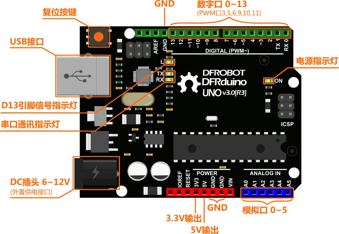
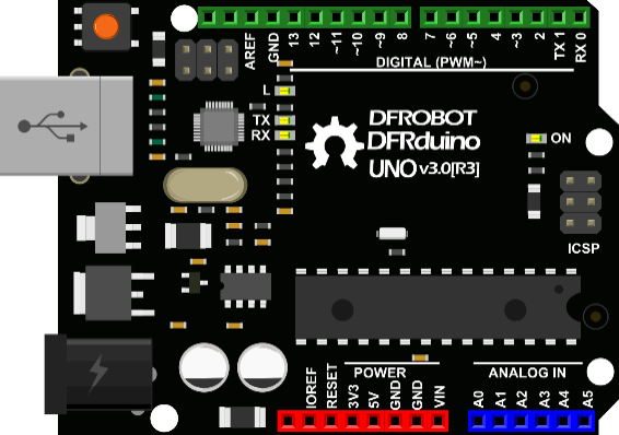
Let’s take a simple look at Arduino UNO. The parts marked in the image below are the commonly used parts. The digital and analog ports marked in the image are what we commonly refer to as I/O. Digital ports range from 0 to 13, and analog ports range from 0 to 5.
In addition to the most important I/O ports, there is also a power section. UNO can be powered in two ways: one is through USB, and the other is through an external 6-12V DC power supply. Besides, there are four LED lights and a reset button. The four LEDs are briefly described: ON is the power indicator light, which lights up when powered. L is an LED connected to digital port 13, which will be explained in a sample in the next section. TX and RX are serial communication indicator lights, which will flash continuously while we are downloading programs.
Getting a Glimpse of the Secrets of Mind+
Between the Arduino board and the computer, we have a USB cable that physically connects the two. But just doing this is like buying various hardware and assembling a computer without software to use these hardware. So how do we establish a connection between these two information layers and start playing with the Arduino board?
The answer is Mind+! It builds a virtual bridge between the two, enabling functions such as code burning, serial connection, and real-time data stream transmission.
The preliminary projects in this tutorial will guide you to use Mind+ for easy graphical programming, helping you better understand the core ideas and implementation steps of the program. Once you are familiar with various instructions, you can try your hand at designing original programs through combinations and gradually attempt to input codes yourself in Mind+! With the previous foundation, the later projects will gradually shift from graphical programming to pure code learning, allowing you to deeply feel its charm as you type in lines of code, letting you slowly release the hand that has been supporting you through graphical programming and run freely in the world of programming!
Now let’s quickly familiarize ourselves with the world of Mind+!
First Use
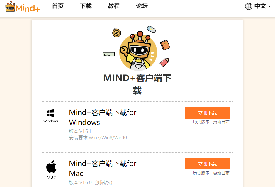
1. Download Mind+ (Download link: http://mindplus.cc)
Mind+ is a youth programming software developed based on Scratch 3.0, supporting various open-source hardware such as Arduino, micro:bit, and control boards. You can complete programming simply by dragging graphical program blocks, and you can also use advanced programming languages like Python/C/C++, allowing everyone to easily experience the joy of creation.
Mind+ download client
* If you encounter any problems during the download and subsequent installation and use, you can visit the official website of Mind+ to find solutions in the FAQ and forum. If you can’t find a solution, you can post in the forum to ask, and technical support will solve your problems in a timely manner!http://mindplus.dfrobot.com.cn
After downloading, double-click to install:
2. Install Drivers
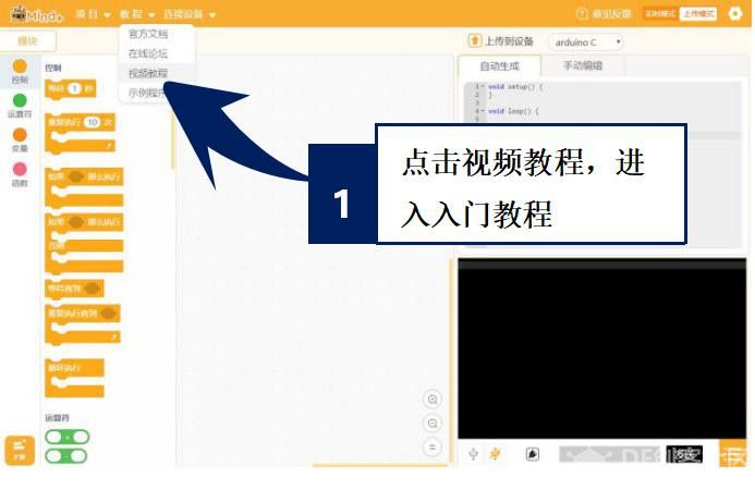
· After successful installation, open the software, click on “Tutorial” – “Video Tutorial” button to open the tutorial, and follow the prompts in the “Install Driver” tutorial to install the driver.
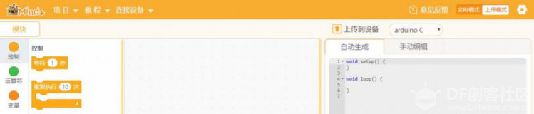
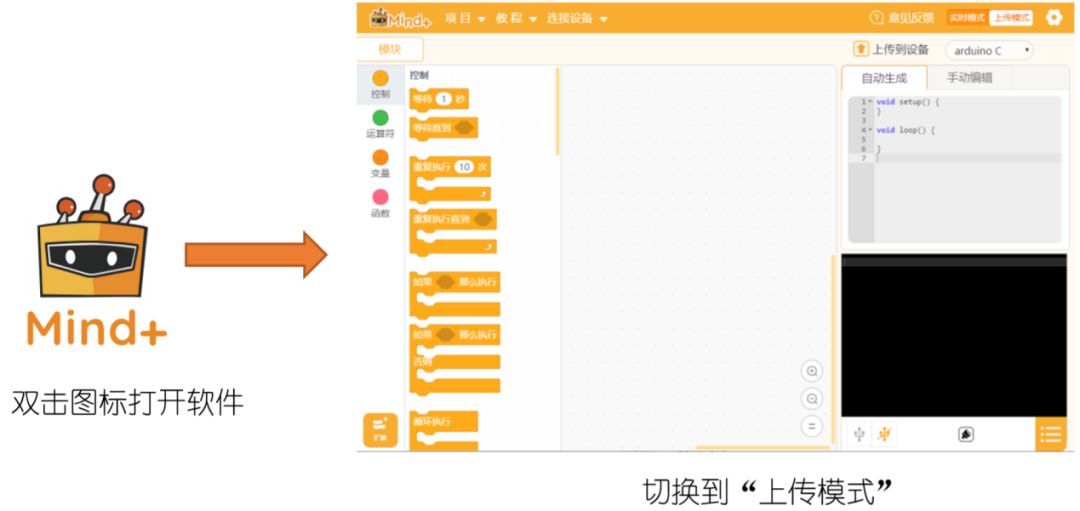
3. Switch to “Upload Mode” (All tutorials in this series operate in “Upload Mode”)
Click the upper right corner “Upload Mode” button and wait for the switch
Successfully switched to “Upload Mode” mode
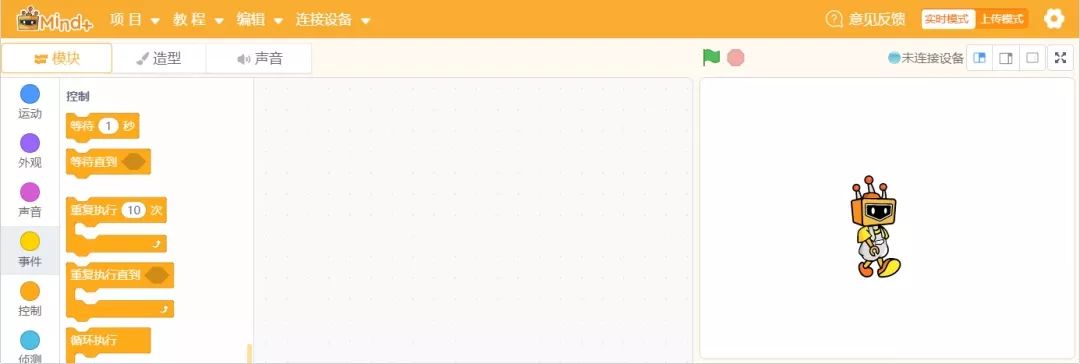
4. Introduction to the Mind+ Interface
After successfully installing, let’s take a closer look at the Mind+ programming interface.
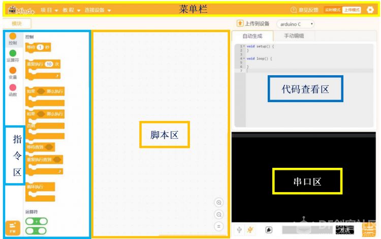
If the entire software is compared to a stage, what are the functions of different areas?
First, let’s look at the menu bar: it is used to set up the software area, which is the backstage of the entire “stage”. Without the help of the menu bar, there would be no opportunity to perform on stage. So what is backstage of the “stage”?
The “Project” menu can create new projects, open projects, and save projects.
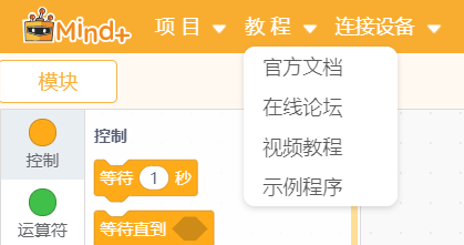
The “Tutorial” menu can be used to find the desired tutorials and example programs during initial use.
The “Connect Device” menu can detect connected devices and choose to connect or disconnect devices.
The “Upload Mode/Real-time Mode” button switches the mode of program execution.
The “Settings” button is used to set the software theme, language, learn basic cases, consult online or join discussion groups.
The Instruction Area: This is the “props” area of the “stage”. To complete various dazzling actions, many different props combinations are needed. In “Extensions”, you can choose more additional props that support various hardware programming.
Script Area: This is the core of the “stage performance”. All “performances” will act according to the instructions in the “Script Area”. Here is graphical programming that everyone can understand. You can write programs here by dragging instructions from the instruction area.
Code View Area: If you want to know what the code of the graphical instructions in the “Script Area” is, this is a good place. You can also manually edit and enter code through the keyboard in “Manual Edit”.
Serial Area: If you want to know how the “performance” is doing, you must interact with the “audience”. This area can display download status, such as whether the program has been successfully downloaded, where it went wrong; program running status; and can also display serial communication data. In other words, if your Arduino UNO board is connected to a sound sensor, you can see the sound value displayed here. There are also: serial switch, scroll switch, clear output, baud rate settings, serial input box, output format control.
Download a “Blink” Program
STEP1: Double-click the icon on the desktop (as shown below) to open the Mind+ software and switch the mode to “Upload Mode”
STEP2: Connect the Arduino board to the computer using a USB cable, and then click “Connect Device” – “COM7-UNO”
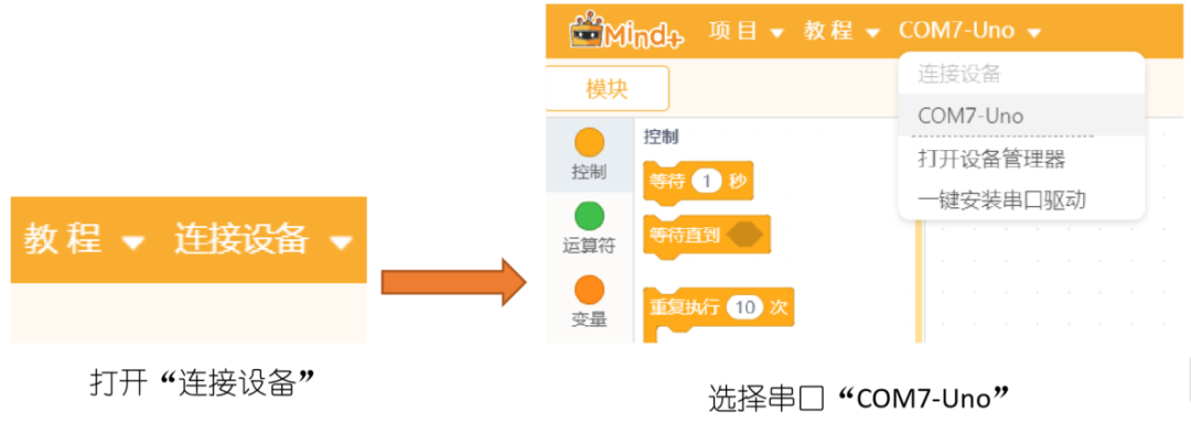
* The 7 in “COM7” may appear as different numbers due to device differences, but it does not affect usage.
* If the COM port does not appear here, please confirm that the Arduino board’s power light is on and that the driver is installed. If you cannot resolve it, please contact us for further assistance.
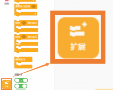
STEP3: Click the lower left corner “Extensions”, and after entering, select the main control board – Arduino UNO

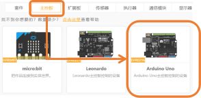
After clicking, you will see that the Arduino UNO module has been loaded.
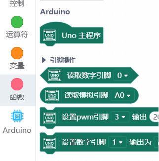
* Do not forget to click on Extensions to add the Arduino UNO library every time you open the software, otherwise, you may encounter situations where instructions cannot be found.
STEP4: Start loading the program by clicking on “Tutorial” – “Example Program”
Click to load the first “Blink”
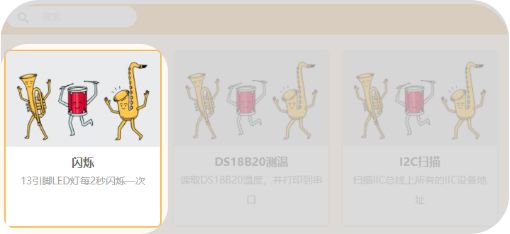
Mind+ has preset the program. Click “Upload to Device” and wait for the program to finish burning.
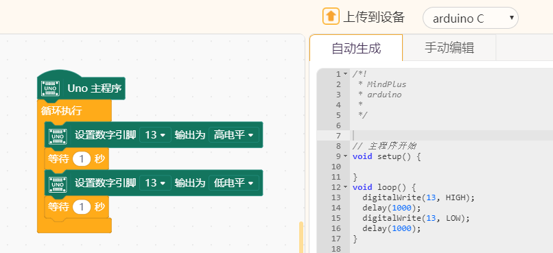
Then you will see the LED light next to “L” on the Arduino board blinking!
——————— End of Text ———————
The purpose of education is to cultivate students’ collaboration ability, communication ability, critical thinking, and creativity, with creativity being the core. Mushroom Cloud Maker Education, as one of the few one-stop maker education service providers in China, aims to cultivate children’s creativity.
To better connect the knowledge students learn in class with the real world, Mushroom Cloud will guide schools to plan, establish, and operate their own maker spaces. Different designs and layouts are made according to the different age groups of students.
Elementary maker spaces focus on fun,
emphasizing interactive scenarios;
Middle school maker spaces focus on practicality,
emphasizing learning scenarios;
High school maker spaces focus on technology,
emphasizing application scenarios;
In terms of content, Mushroom Cloud collaborates with top maker teachers in China to compile a series of textbooks suitable for domestic maker education. It also has a complete maker education curriculum system, including course content and teaching aids, course training, and technical Q&A. Similarly, there will be differences in course classification and design based on the different age groups of students.
Elementary school conducts classes in a gamified and experiential way, focusing on “learning through play”.
Middle school guides students to engage in inquiry-based learning during hands-on activities, promoting “learning through doing”.
High school learning is based on problem and design, requiring teachers to create relevant real-life situations for students to learn through “thinking”.
Recommended Reading:
[Teaching Activity Case] Design a Smart Home Model — Taking the Access Control System as an Example
Mind+: Inclusive and Born for Maker Education!
Virtual Valley Quick Start (V1.0)
Formaldehyde Detection in New and Old Cars — Based on IoT Scientific Inquiry Activity Case
[Virtual Valley IoT and Scientific Inquiry] The Diffusion Process of Salt in Water is “Visible”
What Should We Learn in the Era of Artificial Intelligence?
What are the differences between micro:bit, Arduino, and control boards?
The First Lesson of the School Year, Programming Becomes the Highlight!
US K12 Maker Education Report | Maker Culture – Research on Maker Spaces in American Education
Is it necessary to enroll children in robotics education?
Four Major Issues That Must Be Addressed in Developing Maker Education Curriculum Systems!
I know you are watching!