01
Introduction
The RGB LED is a type of light that achieves various colors by mixing red, green, and blue primary colors. According to the RGB color model, the intensity of red, green, and blue is defined in 256 levels (0 to 255), where 0 means no display and 255 means the brightest. Therefore, by combining the intensities of these three colors, it can display 256 x 256 x 256 = 16,777,216 colors.
02
Principle
LED stands for Light Emitting Diode, made from a mixed compound of gallium (Ga), arsenic (As), and phosphorus (P). Gallium phosphide diodes emit red light, gallium nitride diodes emit green light, and silicon carbide diodes emit yellow light.
The working principle of the RGB LED is based on the light-emitting characteristics of LEDs, which means that when current passes through the semiconductor structure of the LED, it excites the internal electrons to recombine with holes, thus releasing light energy.
Specifically, the RGB LED contains three independent light-emitting chips corresponding to red, green, and blue. Each chip can be independently controlled for its brightness and on/off state. When current flows through these three chips, they emit red, green, and blue light respectively.
By precisely controlling the brightness and on/off state of these three chips, various colors can be mixed. When the three colors of light are mixed in different proportions, rich color effects are produced. For example, when red and green light are mixed in equal proportions, yellow light is produced; when red, green, and blue light are mixed in certain proportions, white light can be produced.
03
Wiring
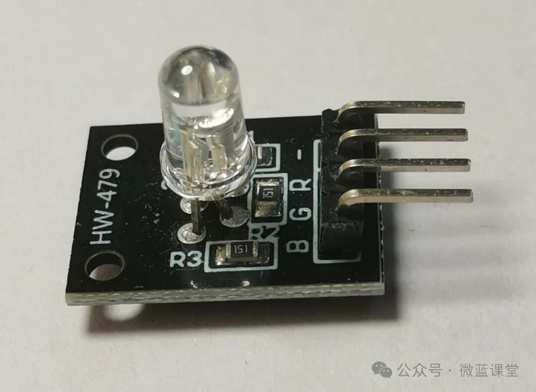
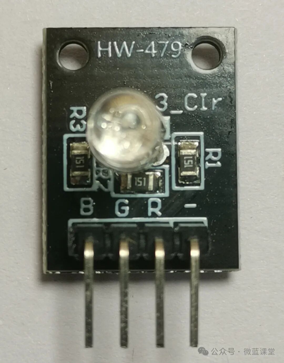
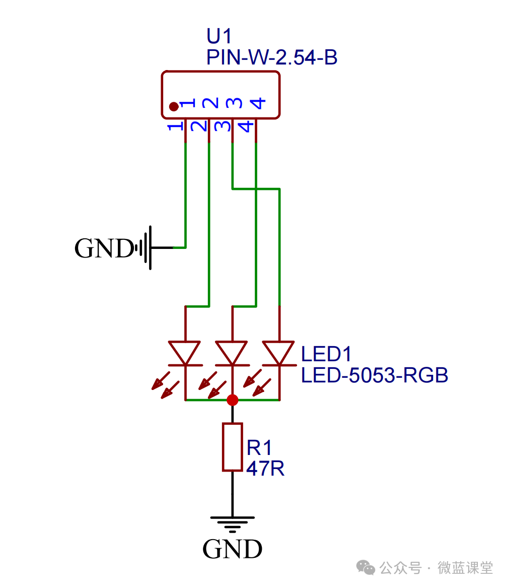
- – : Power negative
- B: Blue control pin, connected to P0
- G: Green control pin, connected to P1
- R: Red control pin, connected to P2
04
Program
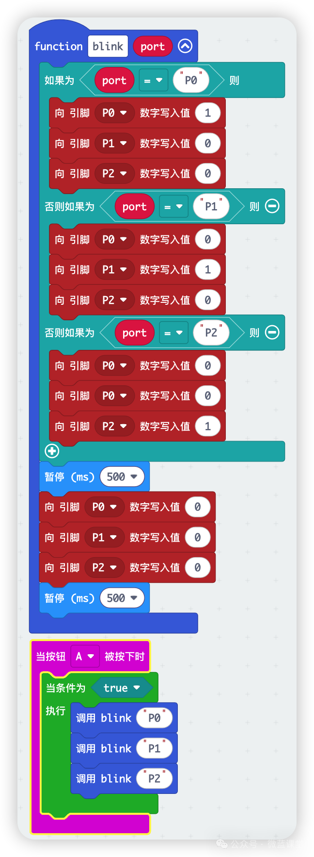
Program Explanation:
Here we implement a simple lighting effect.
First, we define a blink function: if the parameter port is P0, the blue light will turn on for 0.5 seconds, then all lights will turn off for 0.5 seconds; similarly, if it is P1, the green light will turn on; if it is P2, the red light will turn on.
When we press button A on the microbit, it will continuously loop through flashing: blue, green, red.