01
Introduction
The Hall effect sensor is a type of sensor that detects the presence of a magnetic field. Similar to the linear Hall sensor introduced earlier, it does not provide a linear output of magnetic field strength but can only indicate whether a magnetic field is present.
02
Principle
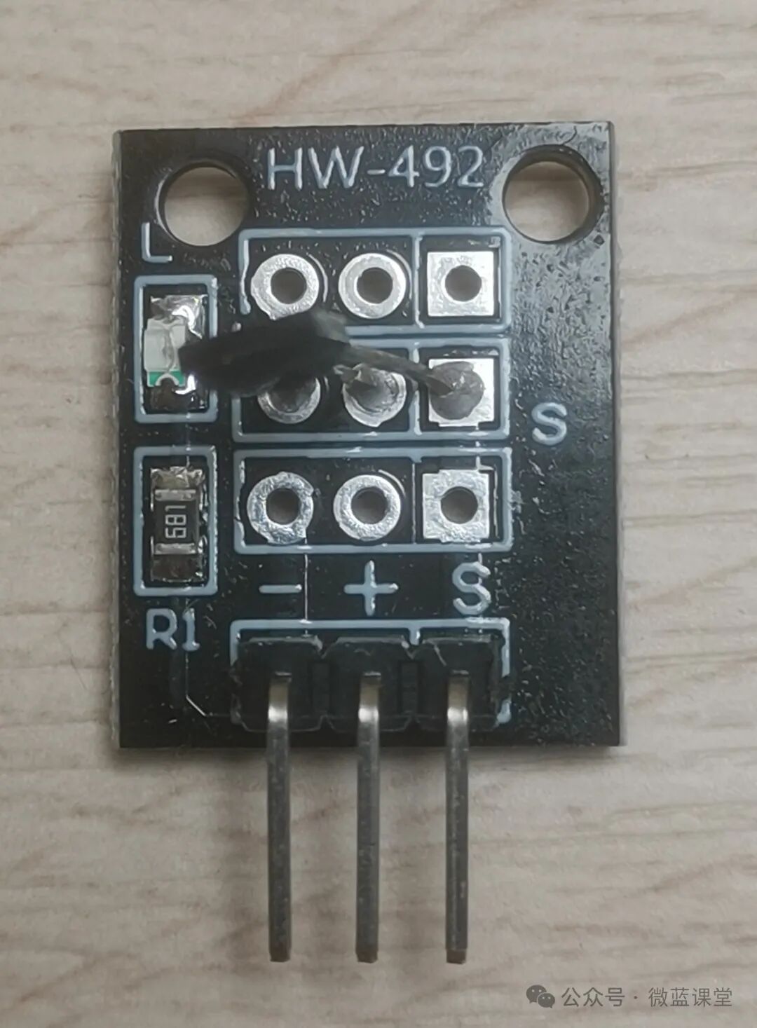
This Hall effect sensor uses the 3144 model Hall element, which has three pins: VCC (positive), GND (negative), and OUT (output). In contrast, the linear Hall sensor uses the 49E model linear Hall element. One side is sensitive to the S pole of a magnet, while the other side is sensitive to the N pole.
It can be used to measure motor speed, digital displays for bicycles, water flow detection, and more.
03
Wiring
- -: Power negative, connect to GND, gray wire
- +: Power positive, connect to 3.3V, red wire
- S: Signal line, connect to P0, blue wire
04
Program
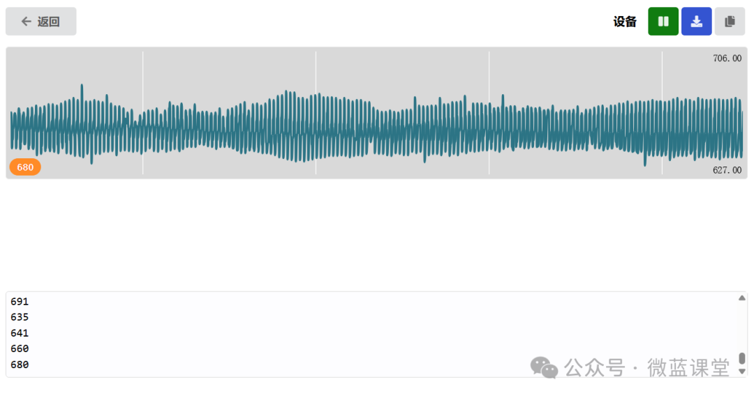
Program Explanation: We observe the data from the S model line via serial communication, with S connected to pin P0, reading in mode.

Below is the oscilloscope graph in a stationary state:
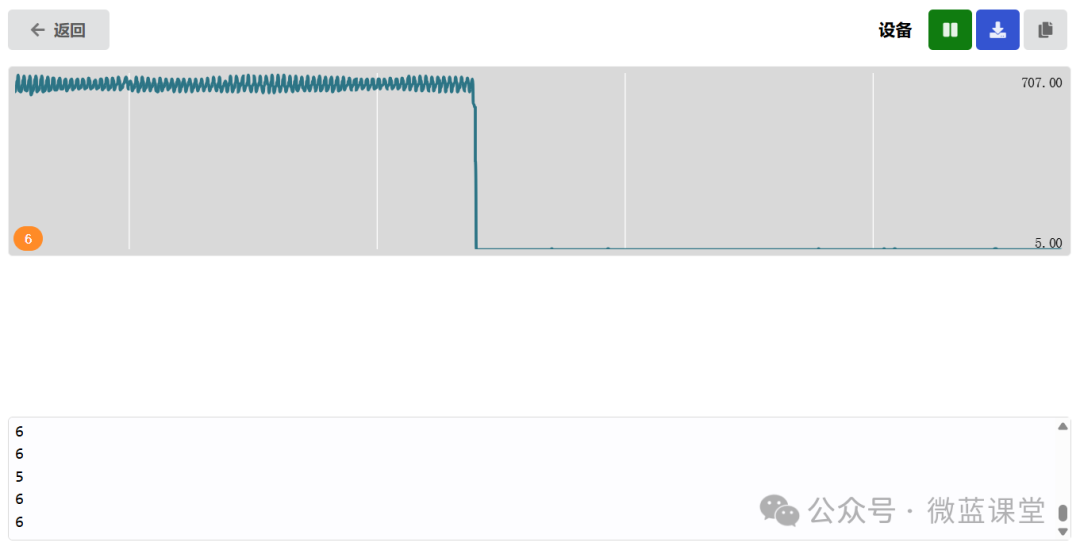
When we bring the N pole of a magnet close to the flat side of the component, the output is 5 or 6, and the graph shows a vertical drop, indicating that the value drops to 6.
When we bring the S pole of the magnet close to the curved side of the component, we get the same result.
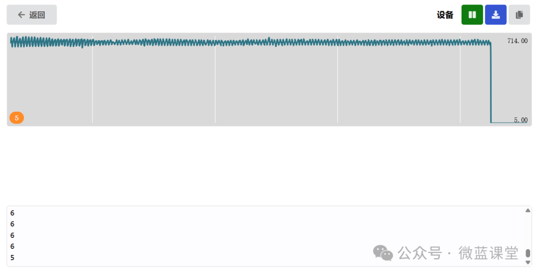
Program Explanation: Based on the observations above, we can determine the presence of a magnetic field by checking if the value is less than 10.