01
Introduction
The high sensitivity sound sensor is a type of microphone that can capture sound more sensitively and convert it into an electrical signal.
High sensitivity sound sensors are widely used in the audio field, such as in recording devices, audio acquisition devices, and voice recognition systems. In these applications, high sensitivity sound sensors can capture subtle changes in sound, providing more authentic and clearer audio signals.
02
Principle
Sound is a mechanical wave. When a sound source emits sound, the sound wave propagates through the air. In high sensitivity microphone sensors, the sound wave first reaches the diaphragm part of the microphone. The diaphragm is a thin film structure that vibrates in response to changes in sound wave pressure. When the sound wave reaches the diaphragm, it vibrates, causing a change in the charge distribution inside the microphone.
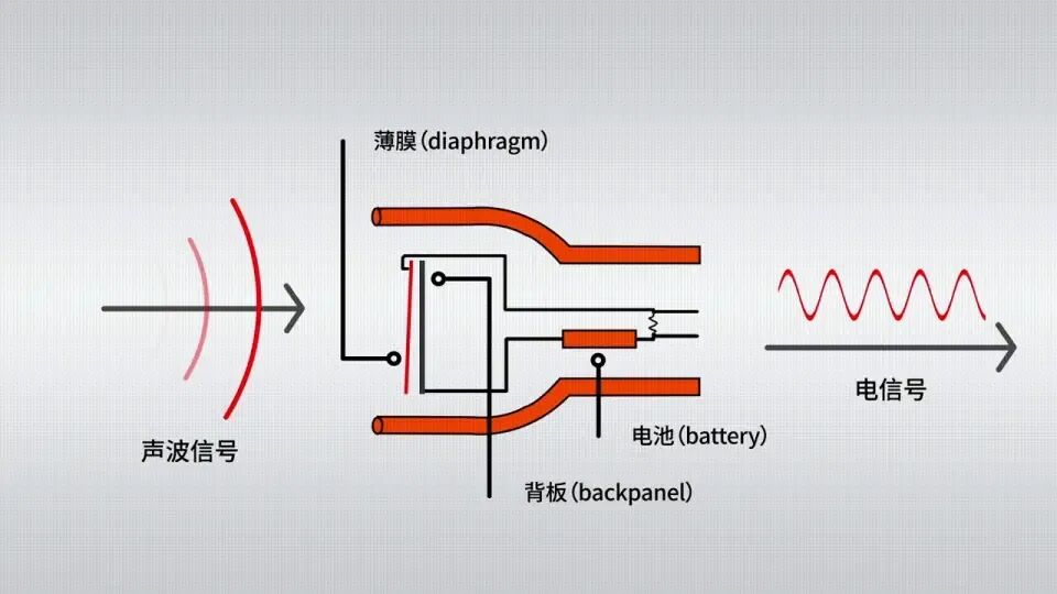
The diaphragm used in high sensitivity microphone sensors is typically made of thin metal or ceramic materials. These materials have good conductivity and mechanical elasticity, allowing the diaphragm to vibrate stably and respond quickly to changes in sound waves.
When the diaphragm vibrates, the charge distribution of the microphone also changes. This is because there are positive and negative metal electrodes on either side of the diaphragm. When the diaphragm moves closer to one electrode, the charge on that electrode increases, while the charge on the other electrode decreases. This imbalance in charge causes a flow of charge, generating a current signal.
03
Wiring
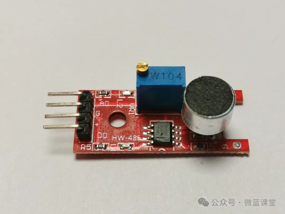
- G: Power negative, connect to GND
- +: Power positive, connect to 3.3V
- DO: Digital output, connect to P0. When the sound intensity reaches a certain threshold, it outputs a high-level signal.
- AO: Analog output, connect to P1, real-time output of the microphone’s voltage signal.
Note: After wiring as above, you need to adjust the threshold. There is a rotating button on the blue W104. If the LED on the sensor is always on, turn the rotating button counterclockwise until the LED turns off. This may require many turns, so be patient. Once it turns off, slowly adjust clockwise to the point just before it turns off.
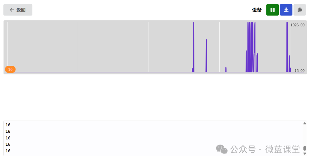
We first observe the data in serial mode. When there is no sound, it is around 16, and when sound is present, the voltage increases.
04
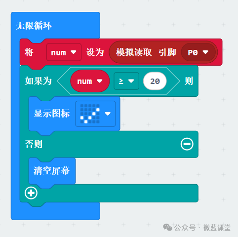
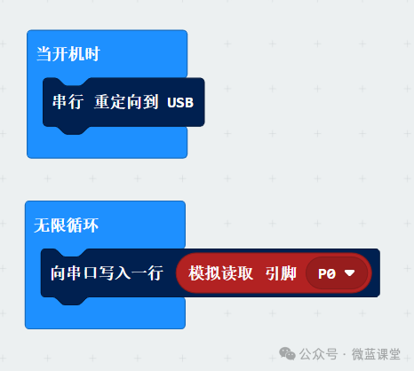
Program
Program Explanation: Continuously detect the value of pin P0. If it is greater than or equal to 20, it indicates that there is sound, and a check mark is displayed.