
Click the blue text above to follow us


Task Control

A certain equipment manufacturer uses a temperature sensor to measure the workshop temperature, with a range of -30℃ to 150℃.
When the measured workshop temperature is -30℃, the current output from the sensor is 0mA, corresponding to a PLC digital value of 0; when the measured temperature reaches 150℃, the sensor outputs a current of 20mA, at which point the digital value received by the PLC is 27648.
Question: When the digital value collected by the PLC is 12000, write a program to calculate the corresponding temperature value.
Implementation of the Task
1. Relationship between Analog and Digital Values
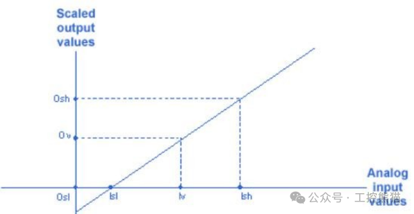
In the 200SMART PLC, there is a specific conversion relationship between analog and digital values, as shown in Figure 1. Here, Lsl and Lsh represent the analog input values of the 200SMART PLC, which range from 0 to 27648.
This means that the PLC automatically converts the 0 – 20mA current signal output from the sensor into a digital value ranging from 0 to 27648.
Osl and Osh represent the range values of the sensor. For example, if the sensor’s measurement range is 0 – 150℃, then Osl is 0 and Osh is 150.
Methods and Suggestions for Writing Analog Programs
There are mainly two methods for writing analog programs: programming based on formulas and using library files for programming. For beginners, writing programs based on formulas is more valuable. Once you master this conversion method, you can flexibly apply it to other PLC programming scenarios. After becoming proficient in formula-based programming, trying to use library files will be much easier. However, here we particularly recommend the second programming method, which is using library files.
Programming Considerations
Before performing programming operations, be sure to complete the configuration settings and select the appropriate measurement signal type, as shown in Figure 2.
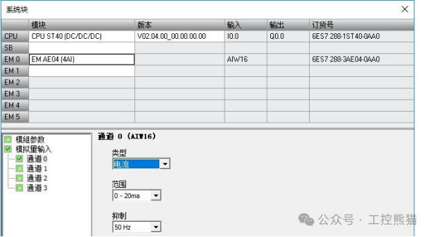
Figure 2
Method 1: Using Global Variables to Write Programs
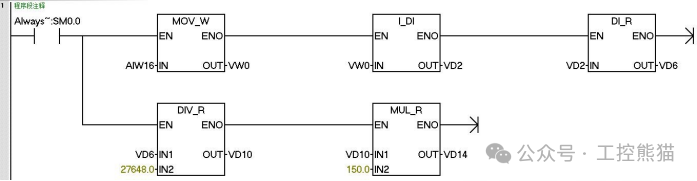
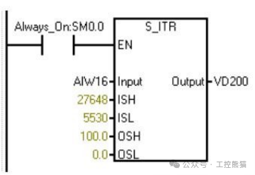
Program Idea: AIW16 is the digital value sent from the sensor to the PLC, with a signal range from 0 to 20mA, corresponding to a range of 0-27648.
Store the collected data in VW0 and then convert it to a floating-point number VD6, finally using division and multiplication to scale the data value to obtain a temperature value with a decimal point.
Method 2: Using Local Variables to Write Programs
The OB1 main program plays a key role in core control within the entire system. It acts like a meticulous commander, systematically coordinating various tasks and functions according to established logic and processes.
By rationally allocating and coordinating system resources, the OB1 main program ensures that the entire system operates efficiently and stably, providing a solid guarantee for achieving the expected control objectives.
In this main program, we will use local variables to achieve specific functions, which not only clarifies the program structure but also enhances the program’s readability and maintainability. Next, let’s explore how to use local variables in the OB1 main program to write programs.
SBR0 Subroutine
The SBR0 subroutine, as an important part of modular programming, undertakes specific functional execution tasks within the system. It acts like a specialized “assistant,” breaking down complex business logic from the main program to independently complete specific operations (such as data processing, device control, etc.), effectively reducing the burden on the main program and enhancing the overall execution efficiency and flexibility of the program.
By using local variables, the SBR0 subroutine can achieve data interaction and parameter passing with the main program and other subroutines, and its results can be fed back to the main program to assist the system in achieving overall control objectives. Next, we will delve into the logic and implementation of writing the SBR0 subroutine.
Program Idea
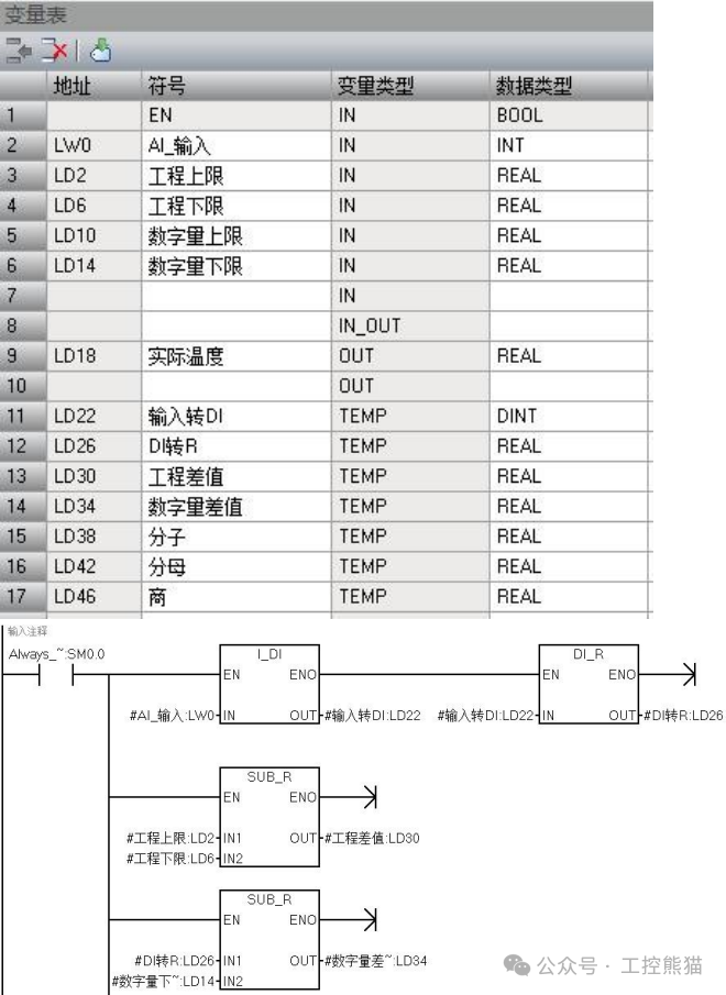
When writing subroutines, it is necessary to use a variable table to define relevant variables. During this process, be sure to correctly fill in the symbol name and variable type. For example, in the sample table, the “Symbol” column should be filled with “Engineering Upper Limit,” the “Variable Type” should be set to “IN” (input), and the “Data Type” should be set to “REAL” (floating-point).
You should flexibly define the variable table according to the actual situation. In this case, a total of 5 input (IN) variables and 1 output (OUT) variable are defined, while the remaining ones are set as TEMP temporary variables. These temporary variables can be used for data temporary storage and processing during the subroutine’s execution to support the smooth progression of program logic.
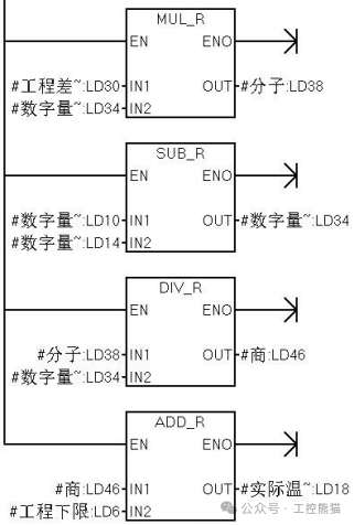
Write the program based on the formula: Formula:

First, convert the collected analog data (#AI_Input) to a floating-point number for easier subsequent calculations. The formula includes addition, subtraction, multiplication, and division; to prevent precision loss, use floating-point operations to ensure high precision.
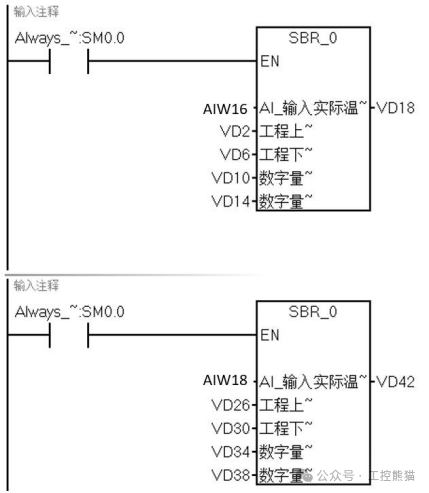
The main program (OB1) can call the subroutine multiple times, filling in the corresponding address, and changing the values in the address will change the temperature measurement results.
Method 3: Using Library Files to Write Programs
Program Idea: To write the relevant program, you can download the S_ITR library file program from the Siemens official website or the Jicheng Training Network, and then load it into the 200SMART programming software. After that, you can directly call the library file program and input the corresponding parameter values to quickly achieve the desired functionality.
Get it for free
The editor has organized today
【22 Siemens Case Program Materials】
Add customer service WeChat

Previous Recommendations
PLC Case | Liquid Mixing Control Program Design (with program)
Method for Writing CRC Check Program in Communication and Device Interaction (with program)
PLC Case | Liquid Mixing Control Program Design (with program)
Useful Sharing: Siemens 200 SMART One-Click Start-Stop Case Analysis (with program)
Super Practical! Mitsubishi FX3U PLC Water Pressure Automatic Control Programming Example (with program)
Practical Sharing: Application Cases of FB Blocks in Mitsubishi PLC GX Works3 (with program)
Understand the S7-200SMART Real-Time Clock, No Worries About Displaying Written Data on MCGS Screen (with program)
Learn to Debug Motor Operation and Frequency Converter Speed Control with S7-1200 PLC (with program)
 Your shares, likes, and views are all appreciatedI like them all