1. Introduction
The alarm system with rotating light project is a typical embedded system application that combines sound alarms and visual indicators. It is widely used in various scenarios such as security monitoring, emergency evacuation, traffic signals, and entertainment devices. Based on the 8051 microcontroller, it provides an integrated sound and visual alarm solution, enhancing the visibility and auditory perception of alarms, especially in noisy or poorly visible environments.
2. Design Concept
2.1 Input Signal Detection
The system detects whether to trigger an alarm through various sensors or user inputs (such as buttons). These input signals can be:
1. Motion sensors detecting movement.
2. Smoke sensors detecting fire.
3. Temperature sensors detecting abnormally high temperatures.
4. User manually triggered emergency buttons.
2.2 Microcontroller Processing
The input signals are captured by the input ports of the microcontroller. The microcontroller processes these signals according to preset program logic and decides whether to activate the alarm and rotating light.
2.3 Alarm (Buzzer) Control
If the microcontroller decides to trigger the alarm, it will activate the sound alarm by controlling the buzzer’s drive circuit. This typically involves:
1. Setting the control port of the buzzer to high or low.
2. Using timer interrupts to modulate the frequency and pattern of the buzzer.
2.4 Rotating Light (LED) Control
Similar to the alarm, the microcontroller will also control the LED light to simulate the rotating light effect. This typically involves:
1. Sequentially lighting the LED lights, controlling the order and timing of lighting through timer interrupts.
2. Using bit manipulation to cyclically shift the lit LEDs to create a rotating visual effect.
5. Timer Interrupts
The internal timer/counter of the microcontroller is key to controlling the frequency of the alarm and the rotating light effect. By setting the timer’s initial value and interrupt service routines, it can achieve:
1. Accurate time delays.
2. Periodic interrupts to refresh the LED light status and modulate the buzzer.
3. Header Files and Macro Definitions
3.1 Header Files:
reg52.h: This is the register definition file for the 8051 series microcontroller. intrins.h: A built-in standard library in C language that includes some intrinsic functions.
3.2 Macro Definitions:
Defines uint and uchar as abbreviations for unsigned int and unsigned char.
#define uint unsigned int#define uchar unsigned char3.3 Parameter Definitions:
The bit value FRQ is used to record the frequency value.
uchar FRQ = 0x00;3.4 Special Function Bit Definitions:
Defines a special function bit SPK, which is a bit variable used to control the 7th bit of port P3 to generate sound signals.
sbit SPK = P3^7;3.5 Main Pin Descriptions:
P3.2: Alarm button. P3.7: Speaker. P2: Eight LED lights used as rotating lights.
4. Function Encapsulation and Purpose
4.1 Delay Function:
Function Parameters:
ms: This is a uint type parameter representing the number of milliseconds to delay. uint is an abbreviation for unsigned int, indicating that this is an unsigned integer variable.
Function Workflow:
The function receives a number of milliseconds as a parameter.
It uses a variable named i of uchar type (uchar is an abbreviation for unsigned char) as a loop counter. uchar is typically used for counters that need less storage space due to its smaller range.
The outer while loop determines the number of iterations based on the passed ms parameter. Before each loop starts, the value of ms is decremented by 1.
The inner for loop is a no-operation loop, with a fixed number of iterations set to 120. The actual purpose of this loop is to consume time, creating a delay.
Delay time calculation:
The delay time of this function is not very precise as it depends on the execution time of the loop. The actual delay time is influenced by multiple factors, including:
1. The clock frequency of the 8051 microcontroller.
2. Compiler optimization settings.
3. The current operating state of the microcontroller and other tasks running.
Code Display:
void Delayms(uint ms){ uchar i; while(ms--) { for(i=0;i<120;i++); }}4.2 Interrupt Function:
External interrupt 0 service function EX0_INT()
void EX0_INT() interrupt 0{ TR0 = !TR0; // Toggle timer 0's running state TR1 = !TR1; // Toggle timer 1's running state if(P2 == 0x00) P2 = 0xe0; // If the value of P2 port is all 0, set it to 0xe0 else P2 = 0x00; // Otherwise clear P2 port}This function is designed to respond to external interrupt 0 requests. In the 8051 microcontroller, external interrupt 0 is usually associated with the P3.2 pin.
TR0 and TR1 are control bits for timer 0 and timer 1, used to start and stop the counting of the timers.
P2 is an 8-bit port register used to control the LED lights or other output devices connected to the P2 port. This function changes the output state by toggling the value of P2.
1. Timer 0 Interrupt Service Function T0_INT()
void T0_INT() interrupt 1{ TH0 = 0xfe; // Reload the high 8 bits initial value of timer 0 TL0 = FRQ; // Reload the low 8 bits initial value of timer 0, using the global variable FRQ SPK = ~SPK; // Invert the state of P3.7 port, used to control the buzzer}This function responds to timer 0 interrupt requests. Timer 0 is used to generate precise time delays and periodic interrupts.
TH0 and TL0 are the high 8 bits and low 8 bits reload registers for timer 0. The values of these registers are reloaded in the function to generate the next timer interrupt.
FRQ is a global variable used to store the period of timer 0 interrupts, allowing the buzzer’s tone to be changed.
SPK is a special function bit connected to port P3.7, used to control the sound of the buzzer.
2. Timer 1 Interrupt Service Function T1_INT()
void T1_INT() interrupt 3{ TH0 = -45000/256; // Reload the high 8 bits initial value of timer 0 for timer 1 overflow time TL0 = -45000%256; // Reload the low 8 bits initial value of timer 0 P2 = _crol_(P2,1); // Circularly left shift the value of P2 port to create the rotating effect of the LED lights}This function responds to timer 1 interrupt requests. Timer 1 is typically used for longer time intervals or periodic events.
By resetting the values of TH0 and TL0, the overflow time of timer 0 can be controlled, affecting the frequency of timer 0 interrupts.
_crol_(P2,1) is an intrinsic function that circularly left shifts the value of the P2 port register by one bit. This is typically used to achieve the rotating effect of the LED lights.
3. Considerations for Interrupt Service Functions:
1) Interrupt service functions are typically used for quick responses to external events, so their code should be as concise as possible to avoid time-consuming operations.
2) Interrupt service functions should restart the paused timers or interrupt sources as early as possible to avoid missing timed events.
3) Modifying global variables or performing long operations within interrupt service functions may affect system stability and responsiveness.
4) Interrupt service functions should avoid using floating-point operations and certain compiler-specific extended features, as these operations may not be usable in interrupt contexts.
5. Main Function
5.1 Code Display:
void main(){ P2 = 0x00; // Initialize all bits of P2 port to 0 TMOD = 0x11; // Set timer mode, configure timer 0 and timer 1 to mode 1 (16-bit timer) TH0 = 0x00; // Initialize the high 8 bits initial value of timer 0 TL0 = 0xff; // Initialize the low 8 bits initial value of timer 0, timer 0 starts counting from 0xffff IT0 = 1; // Set external interrupt 0 to trigger on falling edge IE = 0x8b; // Enable interrupts, allow T0 interrupt, T1 interrupt, and external interrupt 0 IP = 0x01; // Set priority, timer 0 has higher priority than timer 1 TR0 = 0; // Stop timer 0 TR1 = 0; // Stop timer 1 while(1) // Infinite loop { FRQ++; // Increment frequency variable, used to set buzzer frequency in timer 0 interrupt service program Delayms(1); // Call delay function, delay 1 millisecond }}5.2 Function Workflow:
1) Port and timer initialization: The main() function begins by initializing the P2 port and timers, setting them to the desired initial states.
2) Timer mode setting: The TMOD register is used to set the working mode of the timers. Here, both timer 0 and timer 1 are set to mode 1, which is the 16-bit timer mode.
3) Timer initial value setting: TH0 and TL0 are used to set the initial value of timer 0, which will start counting down from this value to 0, then generate an interrupt.
4) Interrupt trigger method setting: IT0 is set to 1, which will set external interrupt 0 to trigger on falling edge.
5) Interrupt enabling: The IE register is used to enable various interrupt sources. In this example, timer 0, timer 1, and external interrupt 0 are allowed.
6) Interrupt priority setting: The IP register is used to set the priority of interrupts. Here, timer 0’s priority is set higher than timer 1’s.
7) Timer start control: TR0 and TR1 control the start and stop of the timers. Here, both timers are initially stopped.
8) Infinite loop: A while(1) loop is used to keep the program running continuously. Inside the loop, the FRQ variable is incremented, and then the Delayms(1) function is called to create a 1-millisecond delay.
6. Simulation Circuit Design
6.1 Simulation Diagram Design:
1. Determine the requirements and functions of the alarm: A sound signal is needed, usually using a buzzer. A rotating light: A visual signal is needed, usually using LED lights.
2. Choose simulation software: Select a suitable simulation software, such as Proteus, Multisim, LTspice, etc.
3. Draw the circuit schematic
1) Place an 8051 microcontroller.
2) Connect P3.7 to the buzzer module.
3) Connect P2.0-P2.3 to 4 LED lights respectively.
4) Add external trigger signals (such as buttons) to the external interrupt pins of the microcontroller.
5) Set the timer parameters to generate the desired interrupt frequency. Use simulation software to draw the circuit schematic, including the microcontroller, input devices, output devices, power supply, etc.
4. Design the circuit
1) Microcontroller: Choose a suitable microcontroller, such as 8051.
2) Input devices: Can be buttons or other sensors used to trigger alarms.
3) Alarm: Use a buzzer as the sound alarm device.
4) Rotating light: Use multiple LED lights to simulate the rotating effect.
5) Power supply: Design the power supply circuit, including voltage regulation and filtering.
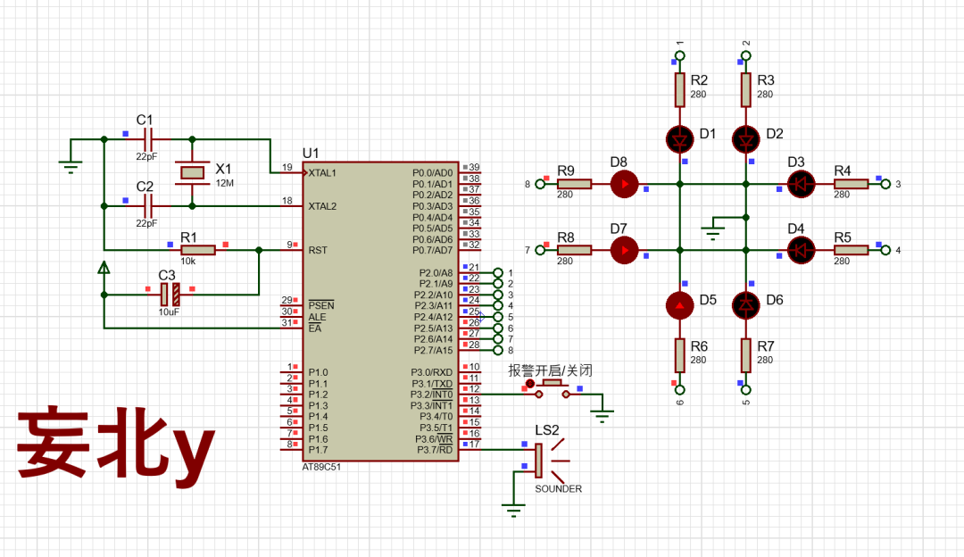
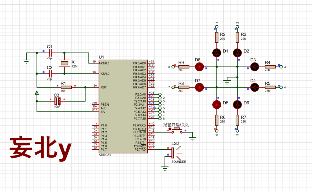
6.2 Simulation Diagram Display:
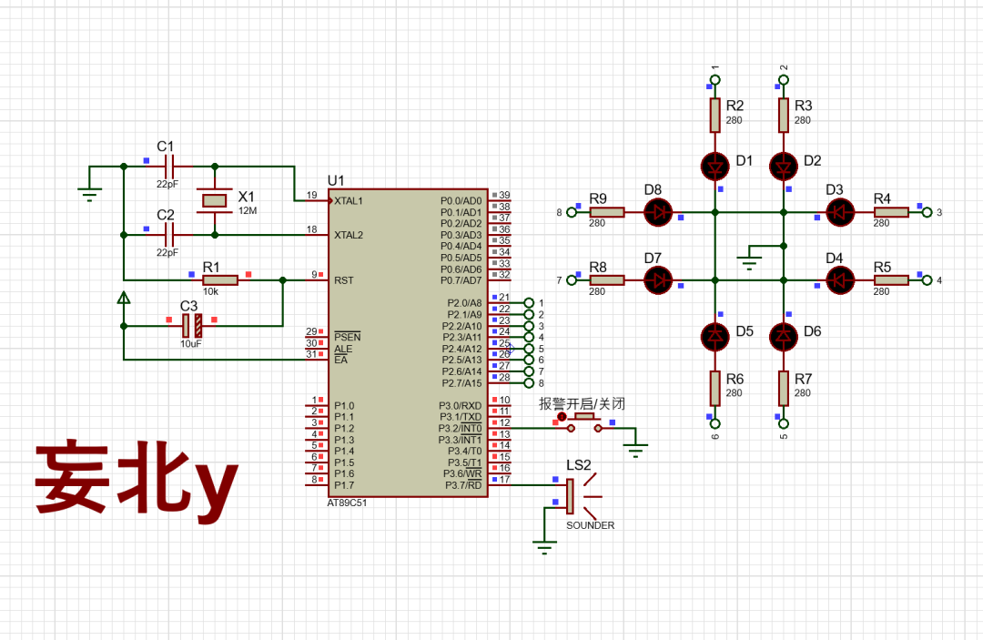
6.3 Function Demonstration:
Before the alarm:
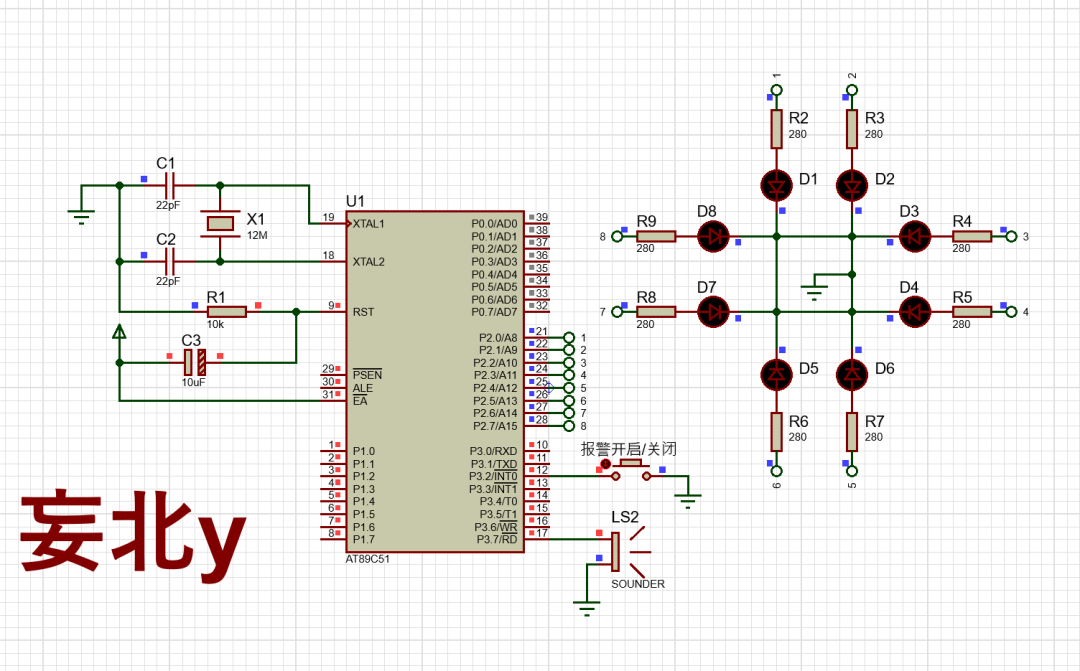
Alarm:
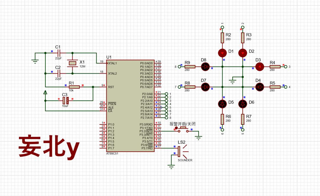
Off: