This is a low-cost 12 DOF quadruped robot using an Arduino-based control board. It has two playback modes. One is autonomous driving mode, where the robot walks and performs random actions. This is the default mode. The other is control mode, where the robot is controlled by an iPhone or Android phone via BLE technology.
For the complete tutorial, please see:
http://ck.mfcad.com/diy/s145.html
Step 1: Print 3D Models
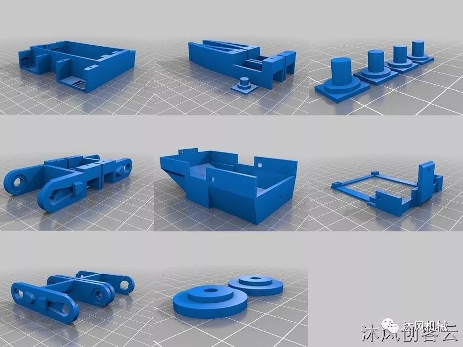
Download the STL model files for 3D printing. The recommended parameters for printing the model are as follows.
Bottom/Top Thickness: 1mm
Shell Thickness: 1.2mm
Layer Height: 0.2mm Fill
Density: 10%
Support: Yes
Attachment Type: Skirt
Step 2: Software
The software can be downloaded for free:
Arduino code (included in the file)
goBLE iOS app on Apple Store (provided by the mainboard seller)
PlayBLE Android app for Google Play (provided by the mainboard seller)
Upload the Arduino code through open firmware.ino in the Arduino software, refer to step 10 on the iOS app and step 11 on the Android app to control the robot.
For HuaDuino, in the Arduino IDE software:
Select board: “Arduino Nano”, processor for AVR board “ATmega328” supports version 1.6.20 or higher.
Select board: “Arduino Nano”, processor “ATmega328 (Old Bootloader)” for AVR board supports version 1.6.21 or newer.
Step 3: Hardware
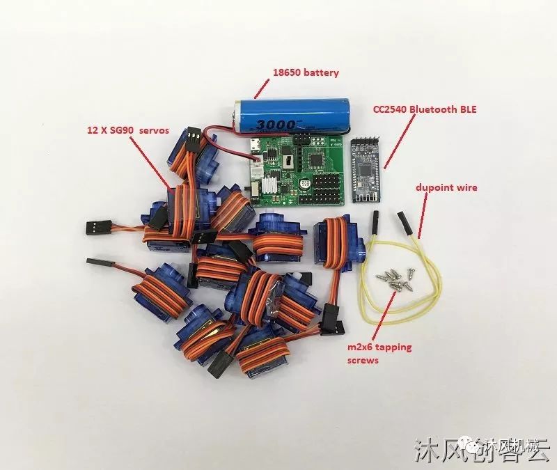
These components can be found in online stores.
A HuaDuino mainboard, Arduino Nano compatible with enhanced features. It integrates everything on a single PCB. It is much easier for people to make robots with it. Embedded battery charging circuit for more convenient battery charging.
A 3.7V 18650 lithium-ion battery or battery pack with XH2.54 connector, if you want longer run time, get a pack with two 18650 in parallel. You may want to use this 18650 battery holder. However, using 3.7V 10440 lithium-ion and 3.7V lithium polymer batteries with dimensions not exceeding W35mm, L70mm, and T60mm is also acceptable.
12 x Tower Pro SG90 or compatible 9g servo system.
A dupont wire or any way you can find to connect two pins
Some m2x6 self-tapping screws
A BT-05 CC2540 Bluetooth BLE module – This is optional if you do not need control from the app. Baud rate needs to be set to 115200. For the iOS app, the service UUID must be set to 0xDFB0, and the characteristic must be set to 0xDFB1. Here is the code that does this automatically. Attached is a reference for the AT command set to configure the CC2540.
Assuming the default baud rate for BLE is 9600, the following Arduino program sends AT commands to set the BLE module service UUID, characteristic ID, and baud rate. To run the module below in HuaDuino, the S1 switch must be set to the BT position.
void setup() { Serial.begin(9600); // change to suit your BLE initial baud_rate Serial.println("AT+UUID0xDFB0\r"); // uuid delay(50); Serial.println("AT+CHAR0xDFB1\r"); // characteristic delay(50); Serial.println("AT+BAUD8\r"); // set baud rate to 115200} void loop() {}The steps to upload the Arduino sketch to HuaDuino for BLE control are as follows
Insert the BLE module, switch S1 to the USB side, open huaduino
Upload the above module installer
Close huaduino, switch S1 to the BT side
Open huaduino, let the BLE module installer run for a few seconds.
Switch S1 to the USB side
Upload the robot program
Switch S1 back to the BT side, the robot can now be controlled via BLE
Step 4: Install Servo System and Control Board
Step 5: Legs
Step 6: Servo Wiring
Connect to the digital pins of HuaDuino as follows:
D2 to right front femur servo
D3 to right front tibia servo
D4 to right front coxa servo
D5 to right rear femur servo
D6 to right rear tibia servo
D7 to right rear servo
D8 to left front femur servo
D9 to left front tibia servo
D10 to left front coxa servo
D11 to left rear femur servo
D12 to left rear tibia servo
D13 to left rear servo
Step 7: Calibration
For the complete tutorial, please see:
http://ck.mfcad.com/diy/s145.html
Using a female-to-female twisted wire between the A5 and 3.3V pins, the robot servos will be set to the default reference angle. This is the state of installing the servo system and making the servo arms cover at the correct angle.
Step 8: Install Servo Arms
Connect the female-to-female twisted wire between A5 and 3.3V pins, place the servo arm on the servo axis
Step 9: Completion
Insert the CC2540 Bluetooth BLE module into the Bluetooth connector on the mainboard, then slide the S1 switch to the BT side, and finally close the robot with the top cover and eyes.
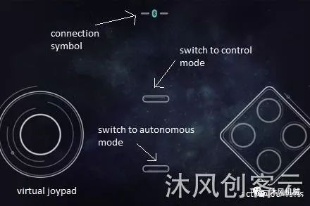
Step 10: Use Control with iPhone
To successfully complete this part, you must configure the CC2540 Bluetooth BLE module, refer to step 3 – Hardware
Open the iOS app and turn on the robot
After a few seconds, the BLE pairing between the robot and the iPhone should be completed, and you will see the connection symbol turn green
Press the top middle virtual button to switch the robot to control mode
Press the bottom middle virtual button to return to autonomous walking mode
Step 11: Control with Android Phone
Open the Android app when the robot presses the connection symbol at the top edge
After a few seconds, you should see the listed BLE devices and select it, the connection symbol should turn blue upon success
Press the top middle virtual button to switch to control mode
Press the bottom middle virtual button to return to autonomous walking mode
Step 12: Battery Charging
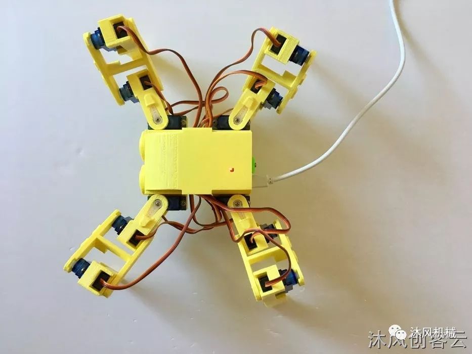
Insert the 5V power micro USB cable into the robot’s USB port
The red light indicates charging
The green light indicates charging is complete