With the rapid development of electronic technology, communication signal frequencies are increasing, and the quality requirements for signals are becoming more stringent. Is it enough to just choose an expensive oscilloscope to measure these high-speed signals? Not necessarily; if some details are overlooked, even the most expensive oscilloscope may not provide accurate measurements!
1. Bandwidth Selection
When measuring high-speed signals, the first consideration is the bandwidth of the testing system, which includes both the bandwidth of the probe and the oscilloscope. To measure a 100MHz signal, is it sufficient to use a 100MHz bandwidth oscilloscope? Some users may not have a clear understanding of the concept of bandwidth. They might think that a 100MHz bandwidth oscilloscope can measure a 100MHz signal, but this is not the case. The bandwidth refers to the frequency at which a sine wave signal is attenuated to -3dB, while the digital signals we generally measure are not pure sine waves but are close to square waves. The bandwidth requirements for these two types of signals are different.
According to Fourier transform, a square wave can be decomposed into odd harmonics of sine waves. For example, a 1MHz square wave is composed of 1MHz, 3MHz, 5MHz, 7MHz, etc., sine waves superimposed together. The following figure shows the response of a square wave signal under different filter settings, including the fundamental frequency of the square wave, the third harmonic frequency, the fifth harmonic frequency, and the seventh harmonic frequency.
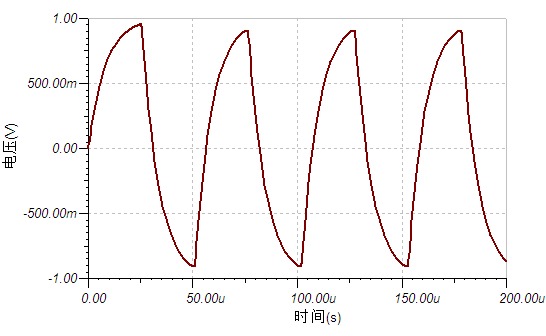
Figure 1: Filtering situation at the cutoff frequency of the square wave frequency
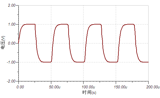
Figure 2: Filtering situation at the cutoff frequency of the square wave’s third harmonic frequency
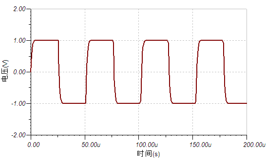 Figure 3: Filtering situation at the cutoff frequency of the square wave’s fifth harmonic frequency
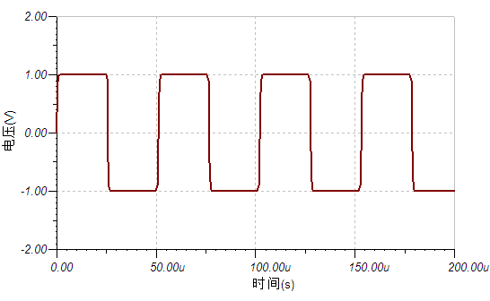
Figure 4: Filtering situation at the cutoff frequency of the square wave’s seventh harmonic frequency
It can be seen that to obtain a relatively complete square wave information, at least the fifth harmonic component is required, and if more accurate information is desired, more harmonic components need to be measured.
Therefore, when selecting the bandwidth of the oscilloscope and probe, it is necessary to choose a bandwidth that is at least above the fifth harmonic frequency of the square wave signal being measured.
2. Probe Selection
The oscilloscope cannot directly measure the signal; it must transmit the signal to the oscilloscope through a physical connection. This physical connection is the probe. The probe is crucial for measuring high-speed signals. Ordinary passive probes generally come in two types: 1:1 probes and 10:1 probes. Besides the different attenuation ratios, these two types of probes can also produce significant differences in high-speed signal measurements. To explain this issue, we need to discuss a key characteristic of probes—loading effect.
Ideally, we want the impedance of our measuring device to be infinite, so that the connection of the testing device does not affect the measured system, thus ensuring the authenticity of the measurement. Unfortunately, it is impossible for the measuring system to have infinite input impedance, and at this point, what impact does the connection of the measuring device have on the measured system? Assume the tested system is as shown in the figure below.
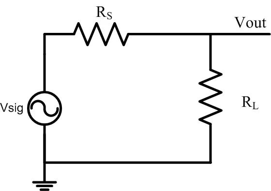
Figure 5: Equivalent diagram of the tested system
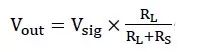
The voltage at the measurement point can be seen:
When measuring with an oscilloscope, due to the input resistance and parasitic capacitance of the oscilloscope, the equivalent circuit diagram at this time is as shown below:
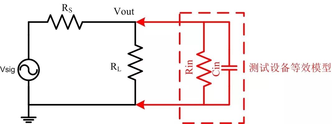
Figure 6: Equivalent diagram of the probe connection
The voltage at the measurement point is now:
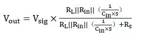
Where Rin is the input impedance, Cin is the parasitic capacitance, and s represents frequency. It can be seen that the voltage at the test point has changed, which leads to a change in the signal itself before and after the probe connection. From the formula, it can be seen that the larger Rin, the smaller the impact on the signal. The term 1/(Cin×s) is the reciprocal of the product of parasitic capacitance and the measurement signal frequency; as the test signal frequency increases, the impact of this term becomes greater. To reduce this impact, the parasitic capacitance Cin must be minimized.
The following is the model of a ×1 probe:
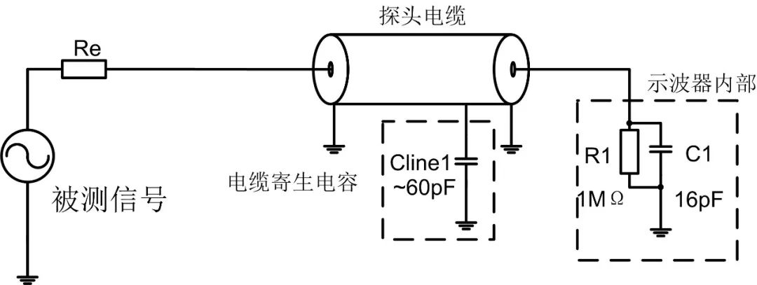
Figure 7: Model of a ×1 probe
Since the probe must have a certain length of wire, otherwise it will be inconvenient for measurement, and the length of the wire generally exceeds 1 meter, this results in a large parasitic capacitance of about 100pF. This causes a significant loading effect when measuring high-frequency signals. Now let’s look at the model of a ×10 probe:
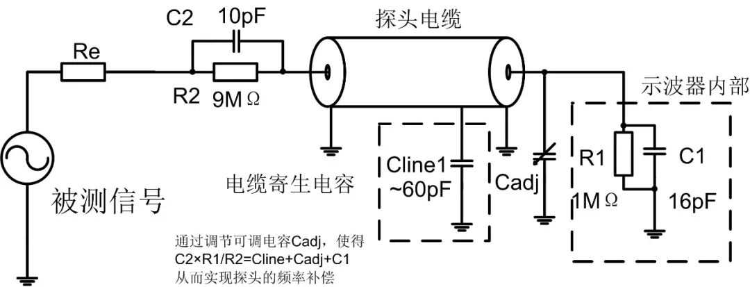
Figure 8: Model of a ×10 probe
It can be seen that the input capacitance Cin of the ×10 probe is 10pF in series with the capacitance behind it. According to the formula for capacitors in series, it can be concluded that Cin must be less than 10pF, which is far less than the input capacitance of the ×1 probe, and Rin has increased to 10MΩ. Therefore, the ×10 probe has a smaller parasitic capacitance and a higher input resistance, significantly reducing the loading effect of the probe.
Thus, when measuring high-speed signals, it is necessary to choose a probe with a ×10 or higher input impedance.
3. Grounding Method Selection
Traditionally, the grounding method for oscilloscopes is the long grounding clip wire. This grounding method is indeed simple and convenient, but it is not a rigorous or accurate grounding method.
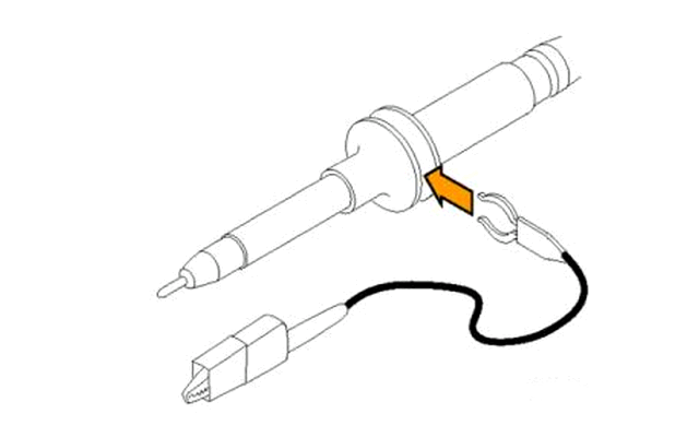
Figure 9: Grounding clip wire diagram
Due to the length of the ground clip wire, it will form a parasitic inductance Lgnd, which increases with the length of the clip wire. This loop inductance will resonate with the input capacitance Cin of the oscilloscope probe, causing the oscilloscope’s amplitude-frequency characteristics to become uneven, leading to inaccurate measurements. The following figure shows the equivalent circuit when using the grounding clip.
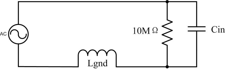
Figure 10: Equivalent circuit diagram of the grounding clip wire
The following figure shows the frequency spectrum characteristics curve simulated using this equivalent circuit:
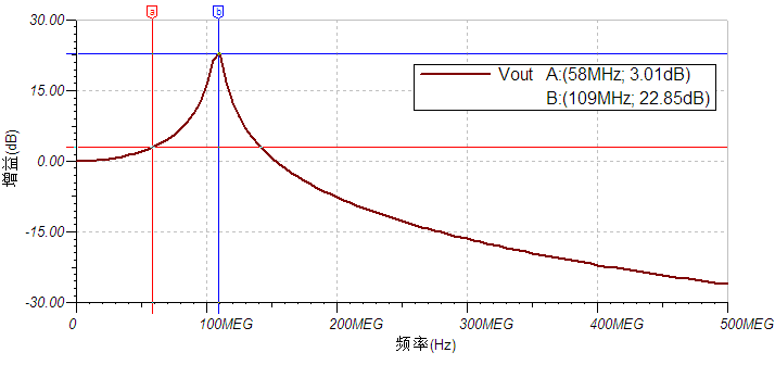
Figure 11: Frequency spectrum characteristics curve
It can be seen that at frequencies above 60MHz, the amplitude has produced more than 3dB of overshoot, and at around 100MHz, the overshoot reaches the maximum amplitude. Therefore, if a ground clip is used, measuring signals above 60MHz will produce significant distortion. The correct method should be to use a grounding spring. The grounding spring has very low inductance, which can greatly enhance the bandwidth of the probe.
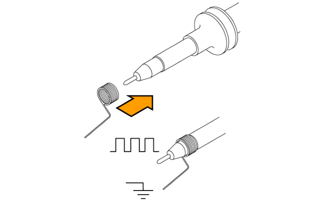
Figure 12: Grounding spring diagram
4. Measurement Position Selection
For high-frequency signals, PCB traces can no longer be treated as short lines; instead, the effects of propagation delay and signal reflection on the lines must be considered. Traditional low-speed signals can ignore the effects of PCB traces because their wavelengths are long, and the length of PCB traces can be neglected, allowing them to be treated as lumped components. However, high-frequency signals have short wavelengths, and the length of PCB traces can no longer be ignored, and the signal must be considered from a wave perspective. The following figure shows the waveforms measured at the source and the terminal of the same signal:
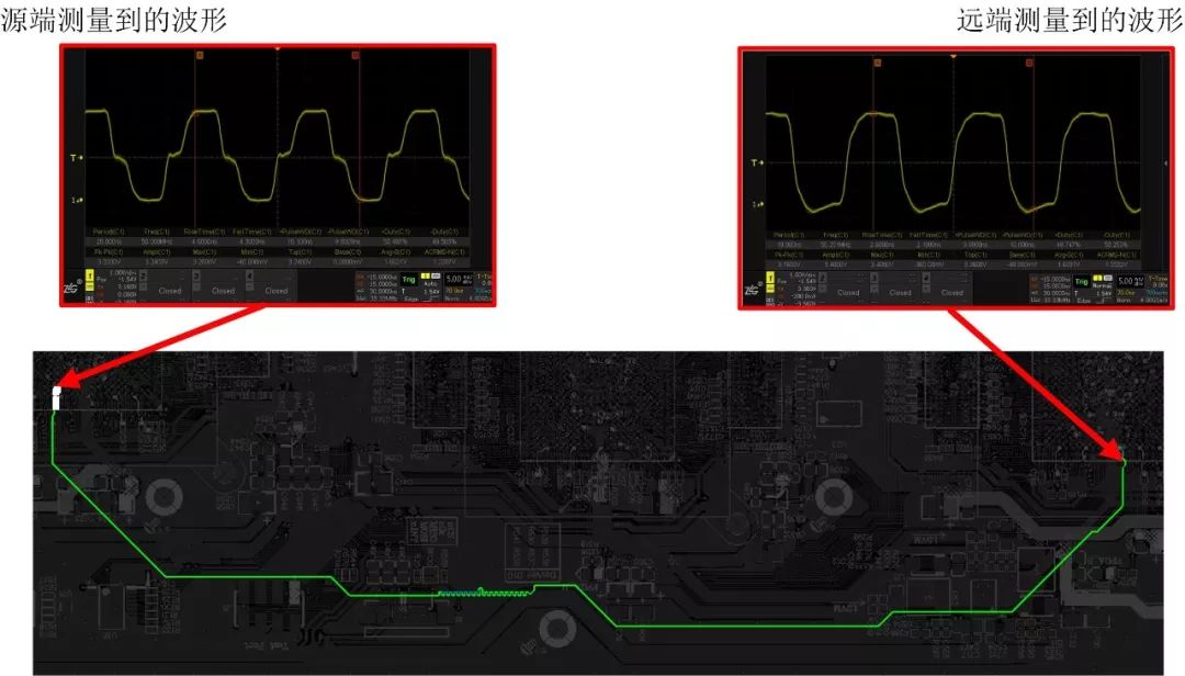
Figure 13: Difference in measurement at different positions
The reason for this is that electrical signals are transmitted on the PCB like waves. Their propagation speed is generally half the speed of light. This causes delays in signal propagation on the PCB, and reflections occur due to changes in characteristic impedance. In the above figure, the terminal device does not have termination, so when the signal reaches the terminal, a reflected wave is generated, which reflects back to the source, and after the delay on the PCB, the reflected wave and the transmitted signal overlap, resulting in the waveform at the source end. Similarly, not only at the source end, but throughout the transmission line, the transmitted signal and the reflected signal will overlap, differing only in their phase differences, resulting in different overlapping waveforms.
It can be seen that the choice of measurement point position can lead to significant differences in measurement results. Therefore, when measuring high-speed signals, the closer the measurement position is to the terminal device, the better, as this allows for a true measurement of the waveform of the signal received by the terminal device.
Conclusion
This article points out some considerations for measuring high-speed signals, summarized as follows:
1. When selecting the bandwidth of the oscilloscope and probe, it is necessary to choose a bandwidth that is at least above the fifth harmonic frequency of the square wave signal being measured.
2. When measuring high-speed signals, it is necessary to choose a probe with a ×10 or higher input impedance.
3. The choice of grounding method should minimize the grounding loop inductance, such as using a grounding spring. This is essential to truly utilize the bandwidth of the measurement system.
4. When measuring high-speed signals, the closer the measurement position is to the terminal device, the better, as this allows for a true measurement of the signal received by the terminal device.
That concludes the main content of this article. The ZDS4054 Plus oscilloscope has a bandwidth of 500MHz, allowing for accurate measurement of 100MHz square wave signals, and with the probe, it can achieve an input capacitance of 9pF, significantly reducing the measurement loading effect, making it suitable for measuring most high-speed signals.
Zhiyuan Electronics Introduction
Guangzhou Zhiyuan Electronics Co., Ltd. was established in 2001 and is a national high-tech certified enterprise, as well as the Guangdong Provincial Engineering Technology Research and Development Center for high-end industrial control measurement instruments.
Vision: To become a leading enterprise in the industrial internet ecosystem
Using the “chip + AWorks software platform” to design high value-added modules, boards, and high-end measurement instruments, connecting to the ZWS IoT cloud through wired and wireless interfaces, enabling big data processing, and forming an industrial internet ecosystem.
Mission: To advance the process of China’s industrial internet with leading technology
Values: Professionalism and focus achieve dreams