★★★EOS-8—IO★★★
Author: Timothy Proofreader: Timothy
Introduction: For various conventional interfaces, we have a good awareness of ESD protection. However, for some discrete or DIY circuits, cross-board usage often also requires ESD protection, such as GOIO, acquisition ports, or cross-board SPI, I2C, etc. This section introduces ESD protection for some IO and cross-board communication interfaces.
€1.Digital IO
There are many methods to protect General Purpose Digital I/O (GPIO). High-frequency signals are usually not suitable for such interfaces, so there is no need to optimize for low-capacitance loads. The three key elements to choose are:
1#: Unidirectional vs. Bidirectional
2#: Single-channel vs. Multi-channel
3#: Package variants
There are many standard devices that can meet these different requirements.
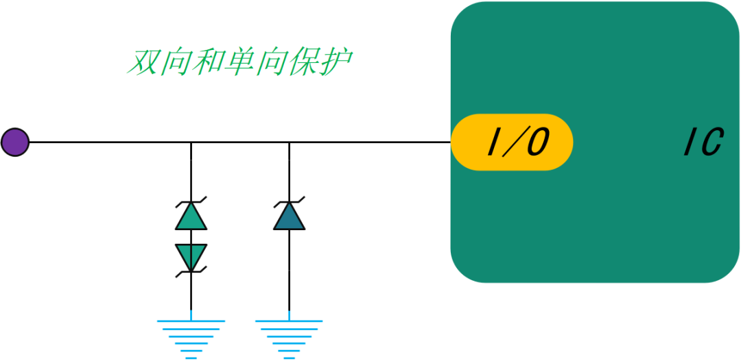
Figure 8-1: ESD Protection for Digital GPIOFor digital IO, it is recommended to refer toTable 8-1:
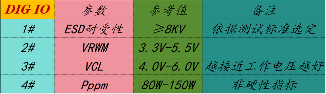
Table 8-1: ESD/TVS Diode Selection Parameters for Digital IO
€2.Analog IO
Although the operating voltage of analog I/O is usually limited, most devices can withstand relatively high voltages for extended periods without damage. For ESD protection, this means that the required reverse blocking voltage (VRWM) must be high enough to avoid conduction at higher voltages. Low leakage current is another requirement for many analog I/O systems, and when precise analog input is needed, it is recommended to limit any external induced leakage loading the analog input, and the protection structure must minimize leakage current.
Various manufacturers provide devices that are very suitable for protecting industrial analog I/O ports, offering higher than standard VRWM, lower leakage current, and smaller PCB area for high-density analog front-end designs. For example, PESD36VS1UL, as shown inFigure 8-2, can be configured in unidirectional, stacked, and other combinations.
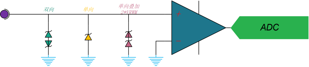
Figure 8-2: ESD Protection for Analog GPIO
For analog IO, it is recommended to refer toTable 8-2:
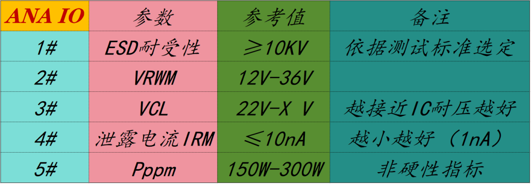
Table 8-2: ESD/TVS Diode Selection Parameters for Analog IO
€3.Low Voltage Comparators
Many microcontrollers integrate analog functions such as comparators, and depending on the connection to the comparator input, ESD protection may be required. As long as the comparator does not operate at very high speeds, protection devices with standard capacitance can suffice.
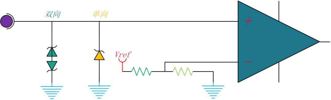
Figure 8-3: External ESD Protection for Built-in Comparators in MCUFor low voltage comparators, it is recommended to refer toTable 8-3:
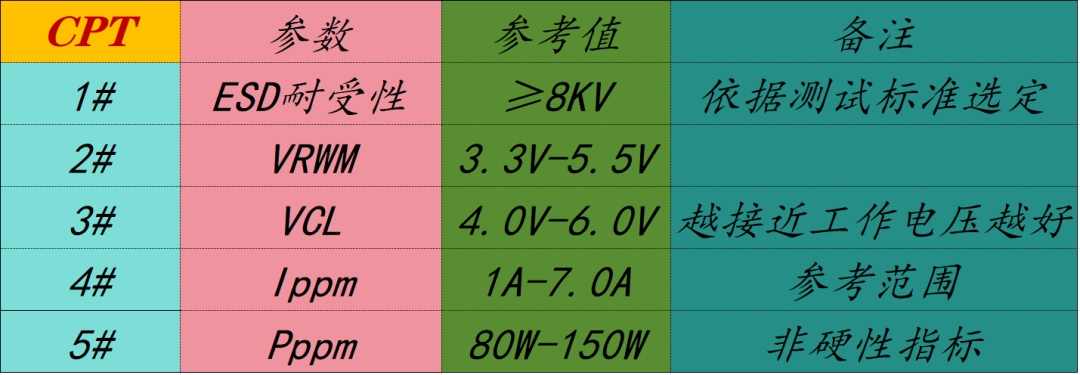
Table 8-3: ESD/TVS Diode Selection Parameters for Low Voltage Comparators
€4.I2C
The speed range of I2C goes from the standard 100KHz to the ultra-fast mode at 5MHz. Figure 8-4 represents two types of rail-to-rail protection configurations, minimizing capacitive line loads, which often provide better performance for high-speed interfaces. The solutions shown here are more suitable for I2C solutions operating at speeds from 100KHz (standard) to 400KHz (fast mode).
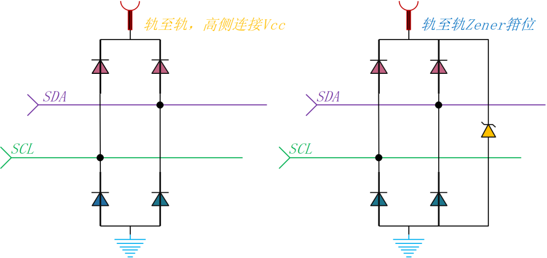
Figure 8-4: ESD Protection Structure for I2CFor cross-board I2C, it is recommended to refer toTable 8-4, such as IP4220CZ6, PRTR5V0U4Y, PRTR5V0U2F.
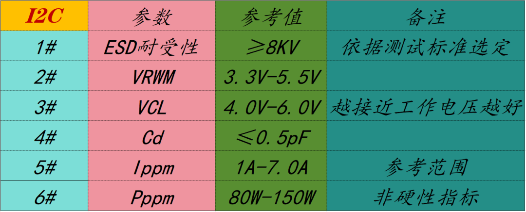
Table 8-4: ESD/TVS Diode Selection Parameters for Cross-board I2C
€5.SPI/SSI
The Serial Peripheral Interface (SPI), also known as the Synchronous Serial Interface (SSI), is a synchronous serial data link that allows devices to communicate in a master/slave mode, with a common clock frequency ranging from 100KHz to 100MHz. If connections are made off the line or through connectors, SPI protection may be required. For low-frequency operation, a basic single-ended protection scheme may suffice, but considering the upper limit of bus frequency, a rail-to-rail implementation is more suitable for general protection.
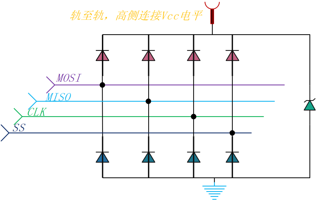
Figure 8-5: SPI Protection Displaying a Single Device with Four-Wire, Rail-to-Rail DiodesFor cross-board SPI, it is recommended to refer toTable 8-5, such as IP4220CZ6, PRTR5V0U4Y, PRTR5V0U2F.
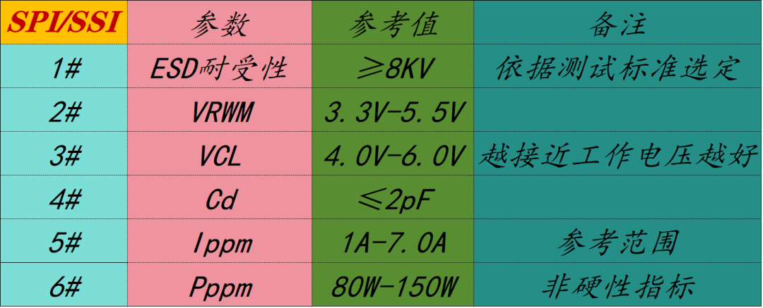
Table 8-5: ESD/TVS Diode Selection Parameters for Cross-board SPI
€6.RS-232/RS-485
There are many devices that are very suitable for protecting RS-485 or RS-232 interfaces. As standard serial ports, RS-485 or RS-232 protection can be unidirectional or bidirectional.Figure 8-6 shows the unidirectional protection of PESD15VS2UT and the bidirectional protection of PESD12LV2BT, with additional series resistors used to further limit the current entering the transceiver.
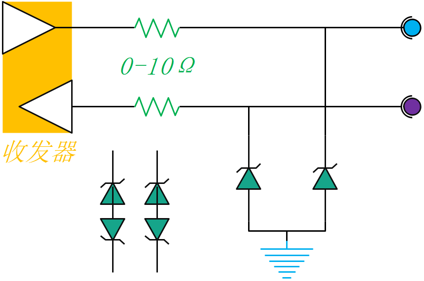
Figure 8-6: ESD Protection Structure for RS232/RS485
For RS232/485, it is recommended to refer toTable 8-6:
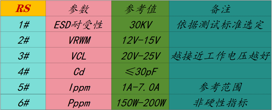
Table 8-6: ESD/TVS Diode Selection Parameters for RS232/485
€7.4-20mA Protection
The 4–20mA signal standard is one of the most popular sensor signal transmission interfaces in industrial applications, with programmable logic controllers (PLCs) providing a voltage source to power the system. Field transmitters and sensors use this power supply to transmit data received from the external environment in the form of 4–20mA current, which is measured by the receiver in the PLC. This 4–20mA loop has the advantage of transmitting data with almost no signal loss. However, due to the long cables of 4–20mA, there is a risk of ESD (IEC 61000-4-2) and surge (IEC 61000-4.5) pulses coupling onto the cables and damaging the system.
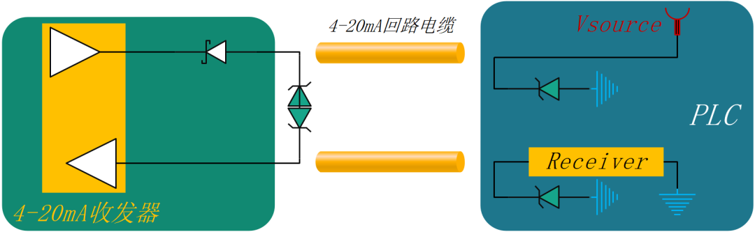
Figure 8-7: ESD Protection for 4-20mA Signal Standard Line
Surge diodes rated for IEC 61000-4-2 and IEC 61000-4-5 must be placed in front of the transmitter, power supply, and receiver to prevent surges or ESD shocks that may couple onto the long cables of 4–20mA. Since most 4–20mA voltage sources are 24V, diodes with slightly higher working voltages are suitable solutions, and since PLC I/O modules and transmitters may be space-constrained, the smaller the protection diode, the better. Recommended devices: TVS3300YZF, TVS3300DRV, TVS3301DRB, TSM36A.
For the 4-20mA signal standard, it is recommended to refer toTable 8-7, where devices with these parameters need to meet both surge protection and ESD protection.
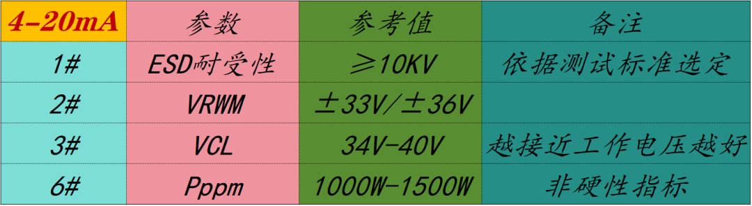
Table 8-7: ESD/TVS Diode Selection Parameters for 4-20mA Signal