MCU Clock Configuration and External Crystal Selection

MCU Clock Configuration and External Crystal Selection

To improve system performance while reducing power consumption, MCUs typically provide four types of clocks: High-Speed External Clock (HSE): Generated by an external high-frequency crystal oscillator. Low-Speed External Clock (LSE): Generated by an external low-frequency crystal oscillator, generally at 32.768kHz, used to drive the real-time clock (RTCCLK). High-Speed Internal Clock (HSI): Generated by an internal high-frequency RC circuit. Low-Speed Internal Clock (LSI): Generated by an internal low-frequency RC circuit, generally at 32kHz, used to drive the independent watchdog.
MCU Clock Configuration and External Crystal Selection
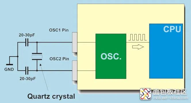
Figure 1. Crystal Oscillator Providing Accurate External Clock for MCU
The benefit of this configuration is that using a single clock at a high frequency may lead to excessive performance and power consumption, while a high frequency may result in insufficient performance to meet requirements. Multiple clocks can balance power consumption and performance.It should be noted that after a system reset, the default initialization is the High-Speed Internal Clock (HSI) to provide sysclock, generally at 16MHz. To enhance system performance, we need to enable the external clock crystal oscillator, such as 24MHz, 32MHz, etc.If using an external HSE, there are generally two modes:(1) External Crystal/Ceramic Resonator (HSE Crystal) ModeThis mode is quite common; HSE crystals can provide a more accurate clock source for the system. The HSERDY bit in the clock control register RCC_CR is used to indicate whether the high-speed external oscillator is stable. At startup, the clock is not released until this bit is set to ‘1’ by hardware. HSE crystals can be started and stopped by setting the HSEON bit in the clock control register RCC_CR.
MCU Clock Configuration and External Crystal Selection
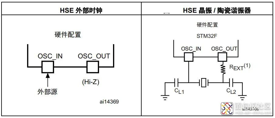
Figure 2. STM32F4 Series MCU Clock Modes
This clock source is formed by the cooperation of an external passive crystal and the MCU’s internal clock driving circuit, which has a certain startup time and high precision, but must be used correctly.(2) External Clock Source (HSE) Bypass ModeThe so-called HSE bypass mode refers to using an external crystal oscillator without requiring the chip’s internal clock driving components to assist, directly importing the clock signal from the outside, as if the internal RC oscillator function of the chip is bypassed.In this mode, an external clock must be provided, and the external clock signal must be connected to the SOC_IN pin, while the OSC_OUT pin presents a high-impedance state to the outside. However, this bypass mode is not as commonly used as the external crystal mode.(3) Example of Crystal SelectionTaking the STM32F4 series MCU as an example, in bypass mode, in addition to configuring HSEON, the HSEBYP bit must also be configured. It is important to note that a passive crystal, specifically a quartz crystal resonator (XTAL), must be chosen as the clock source.First, to reduce clock output distortion and shorten startup stabilization time, the crystal/ceramic resonator and load capacitors must be as close as possible to the oscillator pins, and the load capacitor value must be adjusted based on the selected crystal and other details. As for choosing between ceramic crystals and quartz crystals, it depends on the application circuit’s requirements for frequency accuracy and temperature stability. Generally, quartz crystals have much higher precision than ceramic crystals and much better frequency temperature stability.Secondly, if an active crystal oscillator (XO, TCXO, etc.) is chosen, the user cannot select the operating mode! Since an active crystal oscillator is a complete oscillating device, its clock output does not rely on external oscillating circuit components; it only needs to provide appropriate power to output the clock without additional oscillation drive matching circuits. In this case, we can only configure it as HSE bypass mode, not HSE crystal mode.Furthermore, active crystal oscillators are much more expensive than passive ones; choosing incorrectly not only wastes money but also limits the MCU’s operating modes and user flexibility, which needs to be noted.
Author: Hard City Allchips, Source: Breadboard Community
Link: https://mbb.eet-china.com/blog/uid-me-3975615.html
Show Your Board and Win Prizes

MCU Clock Configuration and External Crystal Selection

Call for Papers: Show Your Board, Share Your Design Ideas and Experiences

01
Activity Prizes

First Prize: 200 Yuan JD E-card

Second Prize: One Furukawa IoT Development Board

Third Prize: Two Physical Books “Operational Amplifier Parameter Analysis and LTspice Application Simulation”

Excellent Participation Award: 20 Yuan JD E-card

02
Requirements and Judging

1. Original, illustrated, with more than 300 words

2. Evaluated based on article length, quality, reading volume, and interaction metrics

Leave a Comment