We believe everyone has read many articles about using a multimeter. The editor has also shared an article titled “Do You Really Know How to Use a Multimeter? A Detailed Explanation of Various Functions and Precautions of the Multimeter.” Mastering the measurement techniques for commonly used electronic components with a multimeter is essential. If you think you know how to use a multimeter well, then check out whether you know the following testing techniques. If you can add a few more tips, it will further showcase your expertise! If you are still unfamiliar with using a multimeter, then these common techniques are something you should master as soon as possible!
1. Testing the Condition of Capacitors
Common faults of capacitors include open circuit, short circuit, and leakage. To test the condition of a capacitor, we typically use the resistance setting on most digital multimeters, which can detect capacitance from 0.1 mF to several thousand microfarads.
When measuring a capacitor, set the switch to the “2MΩ” or “20MΩ” range (the higher the range, the smaller the current flowing from the red probe, so for small non-polarized capacitors, it’s usually best to choose the “20MΩ” range for measurement), then connect the red and black probes to the two leads of the capacitor (for polarized capacitors, ensure the red probe connects to the positive lead and the black probe to the negative lead), and observe the value displayed on the screen.
If the capacitor is normal, the number displayed on the screen will start small and increase (this indicates the capacitor is charging), eventually showing an out-of-range symbol “OL” or “1”. The larger the capacitor, the longer the charging time; the time taken for the number to change from small to “OL” or “1” will also be longer.
If during measurement the displayed resistance value remains “OL” or “1” (indicating no charging process), this may indicate an open circuit or a small capacitance without charging. At this point, you can further use the capacitance measurement setting to check its capacitance. If the capacitance is normal, then the capacitor is functional.
If the displayed resistance value remains “000”, it indicates a short circuit in the capacitor.
If the displayed resistance value can change from small to large but does not reach “OL” or “1”, it indicates leakage in the capacitor.
2. Testing the Polarity and Condition of Diodes
1) Testing the Polarity of Diodes
The polarity of a diode can be tested using the diode measurement setting. During testing, set the switch to the diode measurement range, then connect the red and black probes to any two leads of the diode, measuring in both directions and observing the displayed data each time. The testing operation is illustrated below.
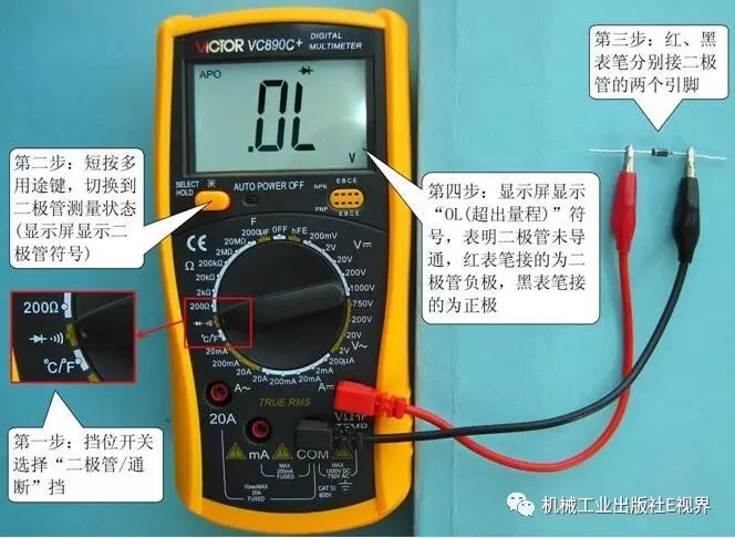
a) When the diode is not conducting during measurement
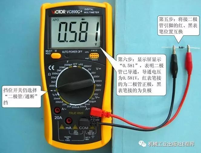
b) When the diode is conducting during measurement
Measuring the Diode
If the displayed number is between 150 and 800 (i.e., 0.150 to 0.800V), it indicates that the diode is in a conducting state, with the red probe connected to the positive lead and the black probe connected to the negative lead. For example, in the above image b, if the display shows “581”, which falls within the range of 150 to 800, then the red probe is connected to the positive lead of the diode, and the black probe is connected to the negative lead.
If the displayed number is an overflow symbol “OL” or “1”, it indicates that the diode is in a cutoff state, with the red probe connected to the negative lead and the black probe connected to the positive lead. For example, in the above image a, if the display shows “1” (or “OL”), then the red probe is connected to the negative lead and the black probe to the positive lead.
While testing the polarity of the diode, you can also determine whether the diode is a silicon or germanium diode. During forward measurement (i.e., red probe connected to the positive lead and black probe to the negative lead), if the displayed number is between 150 and 300, the tested diode is a germanium diode; if the displayed number is between 400 and 800, the tested diode is a silicon diode. Based on this, we can determine that the diode tested in the above image is a silicon diode.
2) Testing the Condition of Diodes
Common faults of diodes include open circuit, short circuit, and poor performance. The condition of a diode can be tested using the diode measurement setting.
During testing, set the switch to the diode measurement setting, then connect the red and black probes to any two leads of the diode, measuring in both directions and observing the displayed data each time.
If the diode is normal, during forward measurement, the displayed number will be between 150 and 800, and during reverse measurement, it will show an overflow symbol “OL” or “1”.
If during both forward and reverse measurements, the displayed number remains “OL” or “1”, it indicates an open circuit in the diode.
If during both forward and reverse measurements, the displayed number remains “000”, it indicates a short circuit in the diode.
If during forward measurement, the displayed number is greater than 800, and during reverse measurement, the displayed number is very large but does not reach “OL” or “1”, it indicates poor performance of the diode.
3. Testing the Type, Pin Polarity, and Condition of Transistors
1) Testing the Type of Transistor
Transistors can be of NPN or PNP type, and the type can be tested using the diode measurement setting. During testing, set the switch to the diode measurement range, then connect the red and black probes to any two leads of the transistor while observing the displayed data. When a number falls within the range of 150 to 800, the red probe is connected to P, and the black probe is connected to N. The testing operation is illustrated in the image below.

a) Measurement Process One
b) Measurement Process Two
Testing the Type of Transistor
2) Testing the Pin Polarity of Transistors
During the transistor type testing, the base pin is identified while determining the type. Next, we will introduce how to identify the collector and emitter pins. Testing the collector and emitter of the transistor uses the “hFE” setting.
During testing, set the switch to the “hFE” setting, then depending on whether the tested transistor is PNP or NPN, find the corresponding transistor socket. Insert the known base pin into the “B” socket, and the other two leads into the “C” and “E” sockets, then observe the displayed value.
If the displayed amplification factor is in the range of tens to hundreds, it indicates that the two leads are inserted correctly, with the lead inserted into the “C” socket being the collector and the lead inserted into the “E” socket being the emitter.
If the displayed amplification factor is in the range of a few to teens, it indicates that the two leads are inserted incorrectly, with the lead inserted into the “C” socket being the emitter and the lead inserted into the “E” socket being the collector.
Below is an example of testing an NPN transistor to illustrate the method for testing the collector and emitter. The testing operation is illustrated in the image below. Set the switch to the “hFE” setting, insert the base pin of the tested transistor into the “B” socket for NPN transistors, and the collector and emitter into the other two sockets. Observe and record the displayed value, then swap the collector and emitter leads, and observe and record the displayed value again. The two measurements will show one larger and one smaller number, with the larger measurement indicating the collector, and the smaller indicating the emitter.
a) Displaying Smaller Values
b) Displaying Larger Values
Testing the Collector and Emitter of the Transistor
3) Testing the Condition of Transistors
(1) Testing the Collector-Emitter Junction and the Emitter Junction (the two PN junctions) for Normal Operation
If any PN junction within the transistor is damaged, it cannot be used. Therefore, the first step in testing a transistor is to check whether both PN junctions are functioning normally.
During testing, set the switch to the diode measurement setting, and test each PN junction of the transistor, measuring each junction in both directions. If normal, during forward testing of each junction (red probe connected to P, black probe connected to N), the displayed number will fall within the range of 150 to 800. During reverse testing of each junction, the displayed number will show an overflow symbol “OL” or “1”.
(2) Testing the Leakage Current Between the Collector and Emitter of the Transistor
A pointer multimeter checks the leakage current between the collector and emitter by measuring the resistance. The larger the resistance, the smaller the leakage current. Digital multimeters can use the hFE setting to directly check the leakage current between the collector and emitter of the transistor. The principle of using the hFE setting to check the leakage current between the collector and emitter is illustrated in the image below.
Using the hFE Setting to Measure the Leakage Current Between the Collector and Emitter of the Transistor
In the image above a, connect the collector and emitter of the transistor to the “C” and “E” sockets of the multimeter, keeping the base pin floating. If the transistor is functioning normally, there will be no conduction between the collector and emitter, meaning the leakage current is 0. No current will flow through R2, resulting in 0 voltage across R2, and thus 0 voltage sent to the IC input, leading to a display of 0 on the screen. If there is leakage between the collector and emitter, current will flow through R2, resulting in voltage being sent to the IC input, leading to a non-zero display on the screen. The larger the leakage current, the larger the displayed number. Image b illustrates testing the reverse leakage current between the collector and emitter, which follows the same principle as testing the forward leakage current.
The operation for detecting the leakage current between the collector and emitter of a transistor is as follows:
Set the switch to the “hFE” setting, keep the base pin floating, and depending on the type and pin polarity of the transistor, insert the collector and emitter into the appropriate “C” and “E” sockets, then observe the displayed value. The normal displayed number should be 0; keeping the base pin floating, swap the collector and emitter leads (i.e., connect the collector to the “E” socket and the emitter to the “C” socket), and the normal displayed number should also be 0. During measurement, if the displayed number exceeds 2, the leakage current between the collector and emitter is significant, and the transistor is generally no longer usable. If the display shows an overflow symbol “OL” or “1”, it indicates a short circuit between the collector and emitter.
Below is a schematic for testing the leakage current between the collector and emitter of an NPN transistor, where the measurement of forward leakage current shows “000”, indicating no leakage current between the collector and emitter.
a) Testing for Forward Leakage Between Collector and Emitter
b) Testing for Reverse Leakage Between Collector and Emitter
Testing Leakage Current Between Collector and Emitter of the Transistor
In summary, if any PN junction of the transistor is not functioning normally, or if there is leakage current between the emitter and collector, it indicates that the transistor is damaged.If during the emitter junction test, the displayed number is “000”, it indicates a short circuit in the emitter junction. If during the test of leakage current between the collector and emitter, the display shows an overflow symbol “OL” or “1”, it indicates a short circuit between the collector and emitter.
In conclusion, testing the condition of a transistor requires six measurements: testing the forward and reverse resistance of the emitter junction (two tests), testing the forward and reverse resistance of the collector junction (two tests), and testing the forward and reverse resistance between the collector and emitter (two tests). Only if all six tests are normal can we conclude that the transistor is functioning properly.
4. Testing Thyristors
1) Testing the Polarity of Thyristors
Thyristors have three terminals: A (anode), K (cathode), and G (gate), as illustrated in image a below. The polarity of the three pins of the thyristor can be determined using the diode measurement setting. The thyristor can be seen as two transistors combined, as shown in the equivalent circuit in image 12-28 (b). From the diagram, it can be seen that there is a PN junction between the G and K terminals of the thyristor.
Thyristor and Its Equivalent Circuit
The operation for testing the polarity of the thyristor is illustrated in the image below. During testing, set the switch to the diode measurement setting, then connect the red and black probes to any two leads of the thyristor while observing the displayed data. When the displayed number is within the range of 150 to 800, the red probe is connected to the G terminal, the black probe to the K terminal, and the remaining terminal is the A terminal.
Testing the Polarity of the Thyristor
2) Testing the Condition of Thyristors
Thyristors are very similar to NPN transistors, so the condition of a thyristor can be tested using the hFE setting. During testing, set the switch to the “hFE” setting, and the testing operation is divided into two steps.
First step: Check whether the A and K terminals conduct without applying a trigger voltage to the G terminal. During testing, connect the A and K terminals of the thyristor to the “C” and “E” sockets of an NPN socket, keeping the G terminal floating, and observe the displayed data. If the thyristor is functioning normally, there will be no conduction between the A and K terminals when the G terminal is floating, and the display will show “000”. The measurement principle and process are illustrated in the image below.
a) Measurement Principle
b) Testing Process
Testing Whether the A and K Terminals Conduct When the G Terminal is Not Triggered
Second step: Check whether the A and K terminals conduct when a trigger voltage is applied to the G terminal. During testing, connect the A and K terminals of the thyristor to the “C” and “E” sockets of the NPN socket, then momentarily short-circuit the G terminal with the A terminal and then disconnect it, which applies a trigger voltage to the thyristor. Observe the displayed data. If the thyristor is functioning normally, after the momentary short-circuit of the G and A terminals, the A and K terminals will conduct, and the display will show a large number (or an overflow symbol “OL” or “1”). The larger the number, the deeper the conduction between A and K. The measurement principle and process are illustrated in the image below.
a) Measurement Principle
b) Testing Process
Testing Whether the A and K Terminals Conduct When the G Terminal is Triggered
If both tests are normal, it indicates that the thyristor is functioning normally; otherwise, the thyristor may be damaged or malfunctioning.
5. Testing the Live and Neutral Wires of AC Power
The identification of live and neutral wires in AC power typically uses a voltage tester. If you do not have a voltage tester on hand, you can also use a digital multimeter to determine this.
Testing the live and neutral wires of AC power uses the AC voltage setting. During testing, set the switch to the AC voltage 20V range, let the black probe float, and then connect the red probe to each of the two AC wires while observing the displayed numbers. You will find that the displayed numbers alternate between large and small; use the larger one as the reference. The wire connected to the red probe will be the live wire. The operation for testing the live and neutral wires of AC power is illustrated in the image below.
a) Displaying Smaller Values
b) Displaying Larger Values
Testing the Live and Neutral Wires of AC Power
This article is excerpted from “Super Simple Learning of Electronic Components (Fully Upgraded Edition)” edited by Cai Xingshan.
Click the image to purchase
Highlights from January’s articles:
Reading List | How to Become an Excellent Electrician or Electrical Engineer? Practical Edition!
Electrical Wiring Standards, One Article is Enough!
To Learn PLC Well, You Must Master This! The Most Common PLC Graphical Programming Languages in IEC61131 Standard!
Why Can Capacitors Charge from a Battery (DC)?
Is Assembling an Electrical Box the Entry Point for Electricians? WORD Brother, First Tell Me the Difference Between a Distribution Box and a Distribution Cabinet!
How to Learn PLC? See How Old Pa Explains It! Full of Useful Information, No Fluff, Guaranteed to Be Read in One Go!
Definitely Worth Collecting! Common Fault Diagnosis and Handling Techniques for Single-Phase Induction Motors!
Chat with Old Pa! As an Electrical Engineer, Where Does Your Greatest Sense of Achievement Come From?
See What Differences Exist Between Electricians in China and Japan When Wiring Indoors?
Four Classic Application Examples of Basic PLC Instructions
The Most Accurate Explanation of the Function of 0 Ohm Resistors!
Basic Electrical Circuit Course for Electricians: Delta-Y and Y-Delta Transformations, Are They Difficult?
Overseas Wiring Tools, A Boon for Electricians! It’s Much More Convenient with It!
Homemade Household Generators, No Fuel Needed, Sufficient Power for the Whole Family! Is It a Scam? Or Are the Experts Hidden Among the People?
Is There Anything Missing in PLC Application Program Design?
Remarkable Article! Easily Teach You to Master Hardware Circuit Design!
How is Three-Phase Power Generated? Understand in Two Minutes!
The First Article of the New Year, If You Don’t Read It, You’ll Miss Out, The Most Comprehensive PLC Programming Algorithms!
You can view all technical articles from 2016 and 2015 by clicking on the menu below the public account “WeChat Directory”→”Article Collection”, or by searching for technical articles based on keywords through “WeChat Directory”→”Search in Account”.
The Mechanical Industry Press E-World WeChat Group Has Been Established
Please click the menu below the public account “More Interaction” – “WeChat Group” to join!