Introduction
The proper operation of the network card is crucial for the system’s network functionality. This article delves into the issues of network card failure due to insufficient reset time, interpreting the reset requirements of different network card chips, circuit design, and key points for driver compatibility, providing engineers with reference for network card design and debugging to help ensure network system stability.
ZLG Zhiyuan Electronics has served a large number of customers since designing ARM core boards, a significant portion of which involves debugging network card circuits and drivers for clients. There are issues with circuit design, driver software, and system network configuration. Sometimes, solving a problem is not simply about hardware or drivers; it requires a multifaceted approach. Looking solely at hardware, aside from schematic design, there are also PCB wiring issues. Below are several practical cases that illustrate aspects of hardware design, PCB wiring, and driver compatibility:
-
Insufficient PHY reset time leading to abnormal network card operation;
-
MDIO source end lacking a 22Ω terminating resistor, causing signal reflection and abnormal network card operation;
-
Poor PCB routing leading to abnormal network card operation.
 Insufficient reset time leading to abnormal network card operation
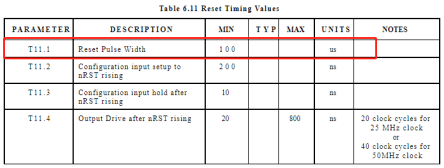
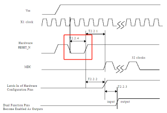
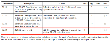
The LAN8720 requires a reset time of no less than 100us (see Figure 1), while the DP83848 used on the reference board requires a reset time of 1us (see Figure 2). Thus, the RC delay parameters used are very small. The parameters for the DP83848 were directly copied onto the LAN8720 circuit, resulting in a reset time that far exceeds the device’s requirements, causing the network card to fail to operate normally.
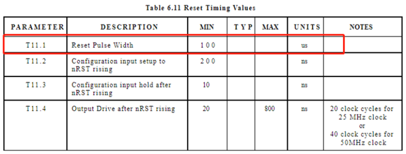

Figure 3 shows the network card circuit used by the customer.
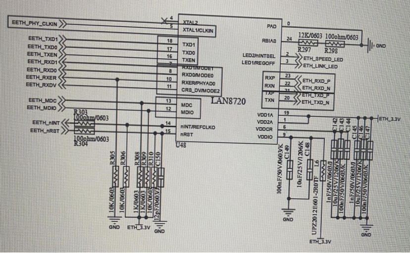
From the circuit diagram, it can be seen that the RC reset circuit has R=10KΩ, C=12pF, and the charging time t = RC: (10^6*12*10^-12) = 12*10^-6 = 12us.
It is essential to strictly design the reset circuit according to the reset time requirements of the network card chip to ensure that the network card chip can reset normally.
The reset time requirements for different network card chips vary greatly, ranging from microseconds to milliseconds. Below is a summary of some common network card reset time requirements.
-
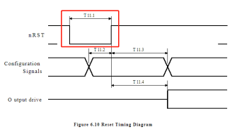
LAN8720: starting at 100us, see Figure 4.
-
DP83848: starting at 1us, see Figure 5.
-
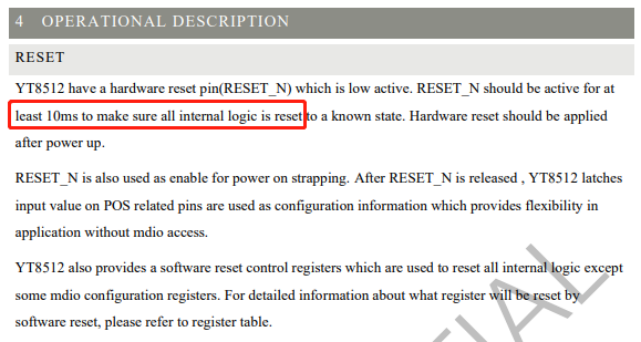
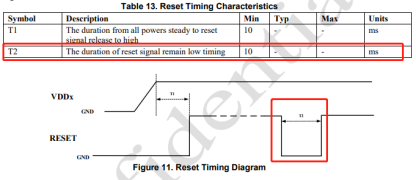
Yutai Micro TY8512/YT8531, starting at 10ms, see Figure 6.
-
ICPlus: IP101G, starting at 10ms, see Figure 7.
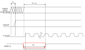
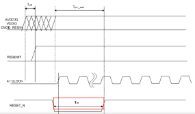
In summary, in general design, it is recommended to use the GPIO of the main control chip to control the reset of the PHY chip, and to parallel the RC circuit near the PHY chip to enhance stability; if the main control chip’s IO resources are tight, an RC delay reset can be used, but it is essential to calculate the required reset time accurately and leave sufficient margin.
-
Moreover, even if the reset time requirements specified in this manual are met, it does not guarantee normal operation. If the design uses the MAC to provide a reference clock to the PHY, the main control’s reference clock may default to input mode, requiring the driver to be loaded and the software configured to output mode. Therefore, it is also necessary to ensure that the Ethernet driver is fully loaded before the reset is released, and these times must be factored into the design of the RC reset parameters.
-
In fact, not only network card chips but also other chips with reset pins need to consider the reset time requirements during circuit design to ensure that the circuit meets the conditions for normal operation.
-
AM335x Upgrade Option
-
2 Gigabit Ethernet
-
3 CAN FD Channels
-
Supports GPMC
Reference price: starting at 319 yuan

Long press to purchase


