Abstract: Yesterday, during the weekend, I came across a video on Douyin that claimed building a small IoT project would cost several hundred dollars. After watching it, I exclaimed that it was quite misleading. Today, I will organize a fun little IoT project from before that I guarantee you can complete in just 10 minutes. Learning is a joy; simplifying a complex topic so that everyone can quickly grasp and implement it is what I enjoy, haha. This article is aimed at beginners with a small demo, so please be kind!
Materials needed: STM32F103C8T6 core board, ESP8266-01S module, DHT11 module (other microcontrollers and Wi-Fi modules can also be used).
The purpose of this project is: the ESP8266 transmits temperature and humidity data to the OneNet cloud platform via the MQTT protocol. The microcontroller used is the most common and cheapest C8T6. Of course, if you are using a different F1 series microcontroller, you can directly copy the code over to use it; it’s that straightforward. The Wi-Fi module used is the beginner-friendly ESP8266, as there’s no need to use something more expensive for writing an article! Of course, if you use another ESP8266, that’s fine too; the AT commands and wiring methods are basically the same. The sensor module used is the DHT11, as this small module can output temperature and humidity information, making it very suitable for geek development.
Using the least amount of money and the most common modules, you can master the basic process of IoT development and implement it in the shortest time, nice
1. Wiring Method
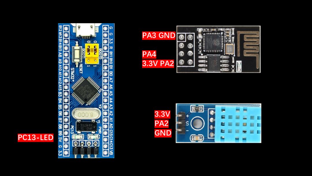
Here, we use the ESP8266, but other modules can also be wired in this manner.
ESP8266-01S (5 wires)
        PA2 -> RX
        PA3 -> TX
        PA4 -> Reset
        3V3 -> VCC
        GND -> GND

DHT11 (3 wires)
      PA6 -> DATA
      3V3 -> VCC
      GND -> GND
LED (usually there is an LED on the core board)
     PC13 -> LED1
2. Program Code
Main idea: Write the interrupt handling function in the stm32f10x_it.c file. USART1 is used for communication with the host computer to print some debugging information. USART2 is used for communication with the ESP8266 and handles the data sent from the host computer via interrupts. Timer2’s interrupt is used to send temperature and humidity data, sending data every 10 seconds. Timer3’s interrupt is used to send heartbeat packets (ping, used to maintain the connection with the server; if no data is sent to the server for a long time, it will be kicked offline), with two modes: 2 seconds and 30 seconds. Timer4 stores the server data received on Serial Port 2 sequentially in the MQTT receive buffer array, processing it every 50ms. Control is used to control the LED light and send the LED switch signal.
This article does not discuss the main implementation of the code; the core part of the code is the MQTT communication protocol and using the AT command set to connect the ESP8266 to the server. I have already explained the principles of this code in detail in previous articles, so I won’t repeat it here. I will mainly discuss the parts you need to modify after you get the code to help you implement it quickly.
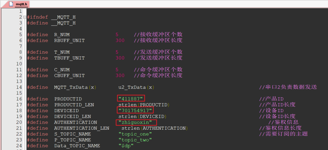
1. mqtt.h
#define PRODUCTID "411887" // Your product ID
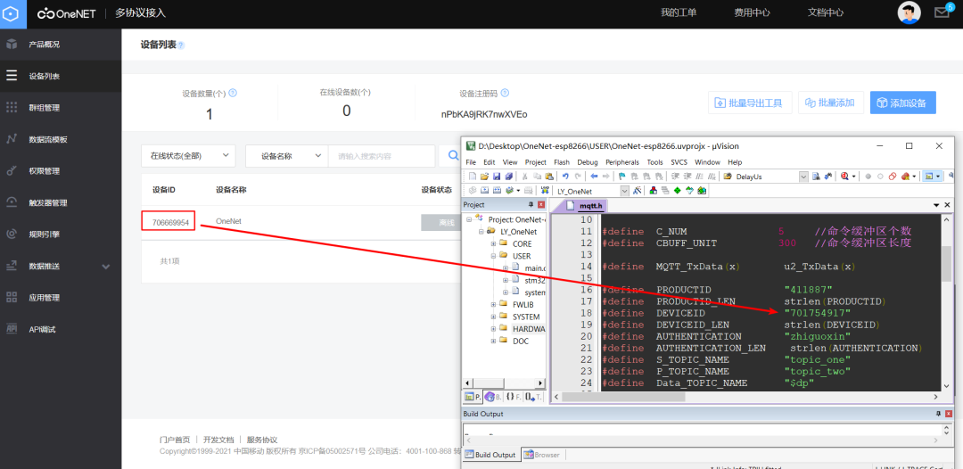
#define DEVICEID "701754917" // Your device ID
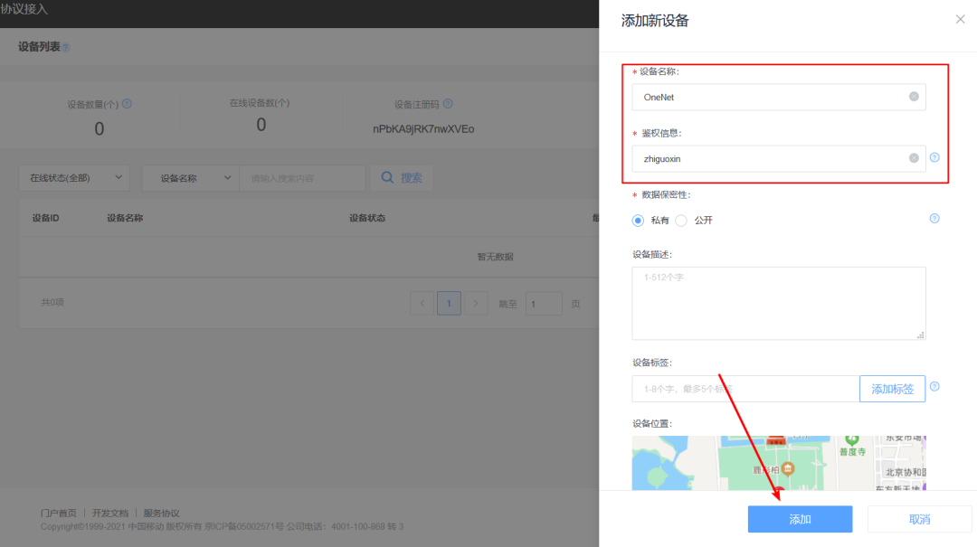
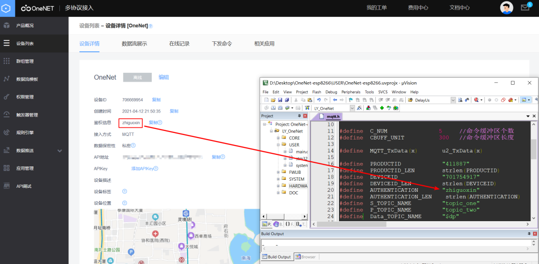
#define AUTHENTICATION "zhiguoxin" // Your authentication information (set when creating the device)
2. mqtt.c
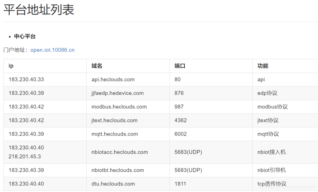
sprintf(ServerIP,"%s","183.230.40.39");  // Build server domain name (ONENET)
ServerPort = 6002;                       // Server port number 6002
Fill in according to the platform address list; here is for the MQTT protocol.
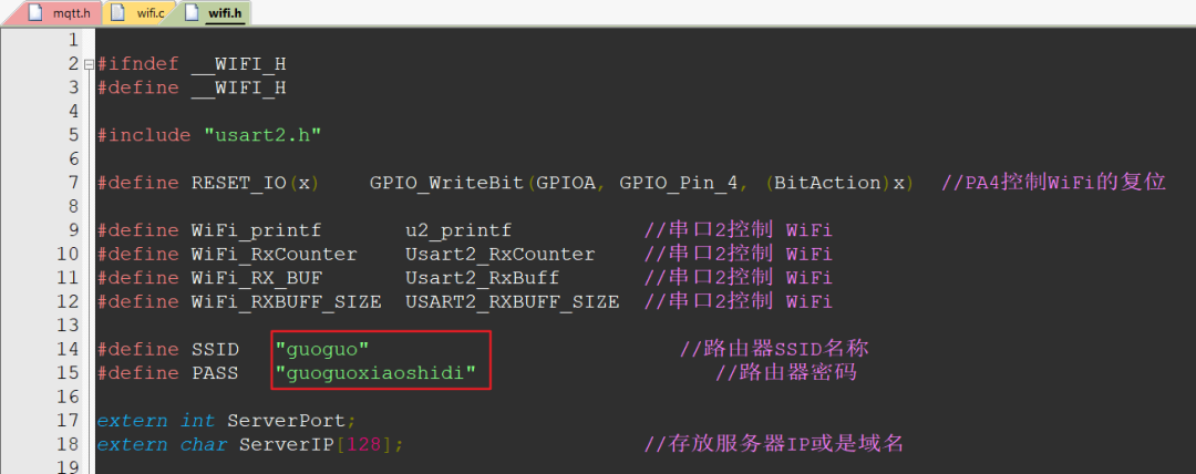
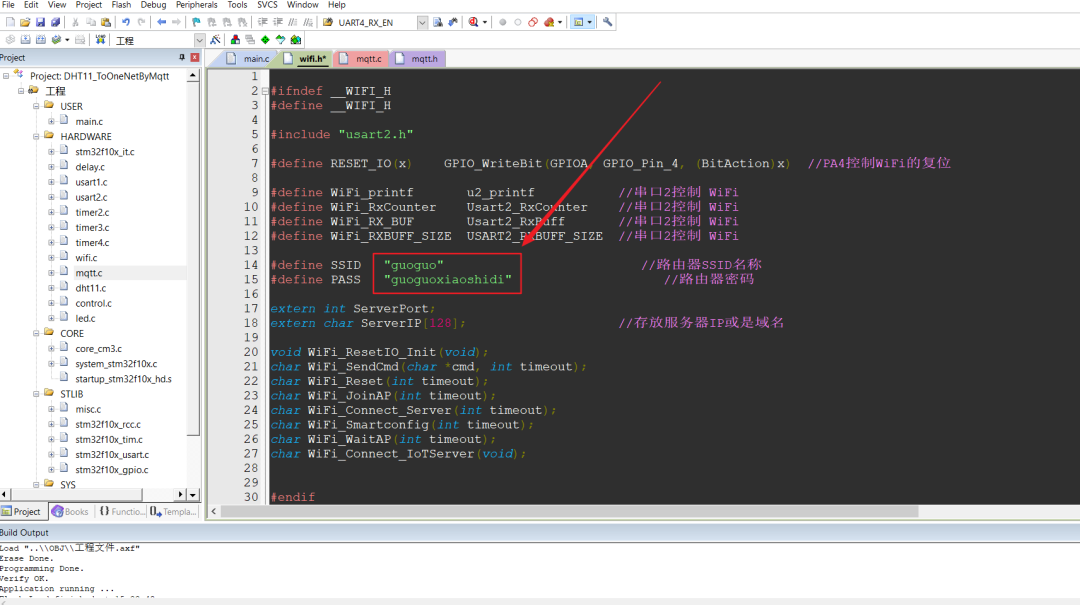
3. wifi.h
#define SSID   "guoguo"           // Your router name
#define PASS   "guoguoxiaoshidi"  // Your router password
3. Cloud Platform Environment Configuration
-
Cloud platform configuration:
-
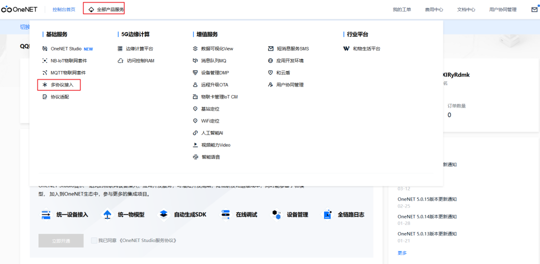
OneNET console—All product services, multi-protocol access—Add product—Enter product—Device list—Add device—Create complete
-
Platform application settings:
-
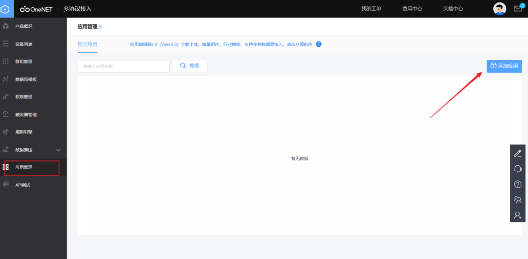
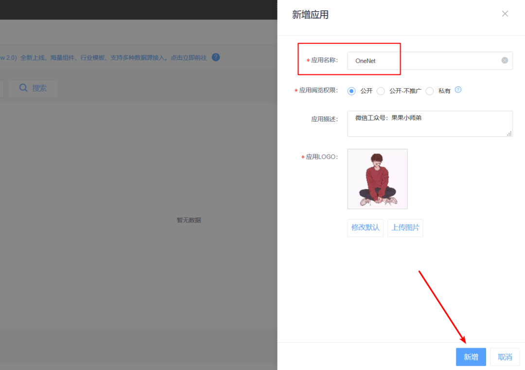
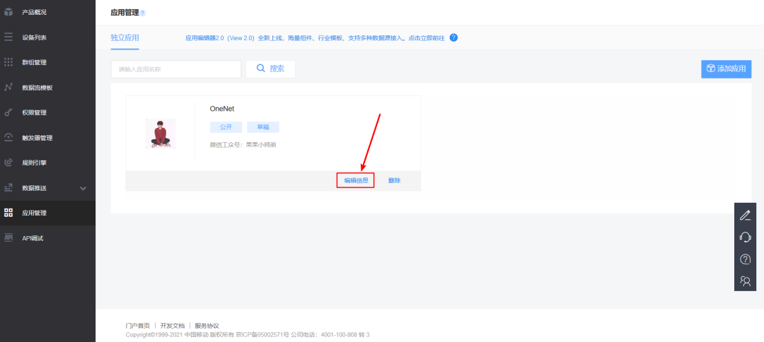
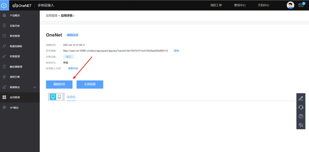
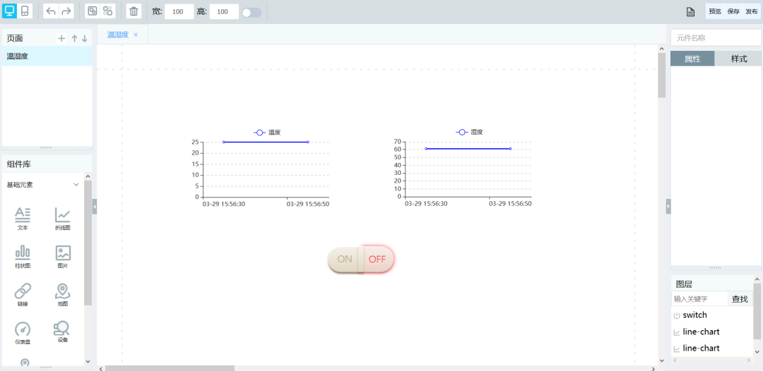
Add application—Edit application—Add line chart and switch in component library -
Line chart: Select data stream — Select device — Choose the data to display from the data stream -
Switch (configure after data upload success): Select data stream — Select device — Choose the data to display from the data stream (here select LED, ledFlag) — Switch on value — Switch off value
4. OneNet Platform Operations
1. Register on OneNet Platform
Just search for the OneNet IoT platform on Baidu, enter the official link, and then register.
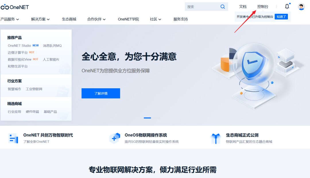
2. Add Product
1. After registration, enter the console, select multi-protocol access; this is the old version that is free, isn’t that great? You can send as much as you want!
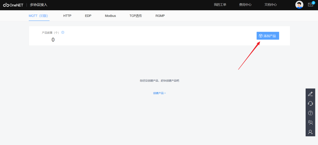
2. Then add a product; this means that since I want to make a product and project, I need to add a product, just like creating a new project.
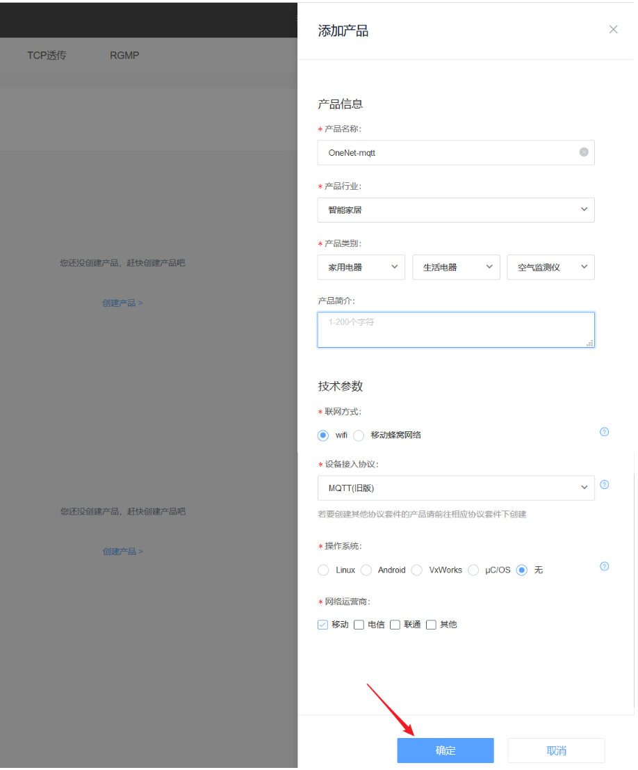
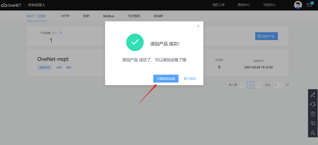
3. Complete the product information; here we can fill in casually.
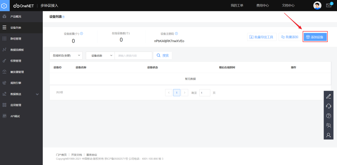
3. Add Device
1. After successfully adding the product, you can add devices. Here, devices refer to your hardware; your STM32, ESP8266, and DHT11 are your devices.
2. Complete device information.
4. Modify Program
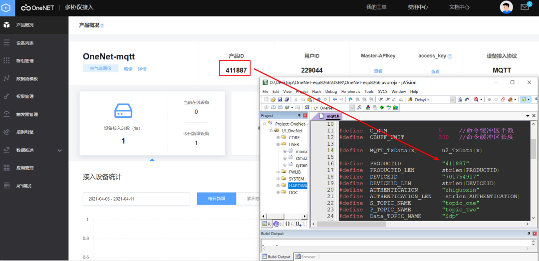
Now you need to connect your module to the platform. The product ID, device ID, and authentication information are the keys and identity cards for your hardware platform to access the OneNet platform; only with the ID number can you connect to the cloud platform, otherwise, you will be kicked off the platform.
1. Next, you need to modify the program in four places, as mentioned earlier regarding the docking information. The first place is to modify the product ID in the program.
2. The second place is to modify the device ID.
3. The third place is to modify the authentication information.
4. The fourth place is to modify the Wi-Fi name and password; you need to let your ESP8266 module connect to the network, and your module should connect to the network before accessing the cloud platform.
5. Download Program
1. After compiling the project, you can download the program, and you will also see debugging information displayed on the debugging assistant.
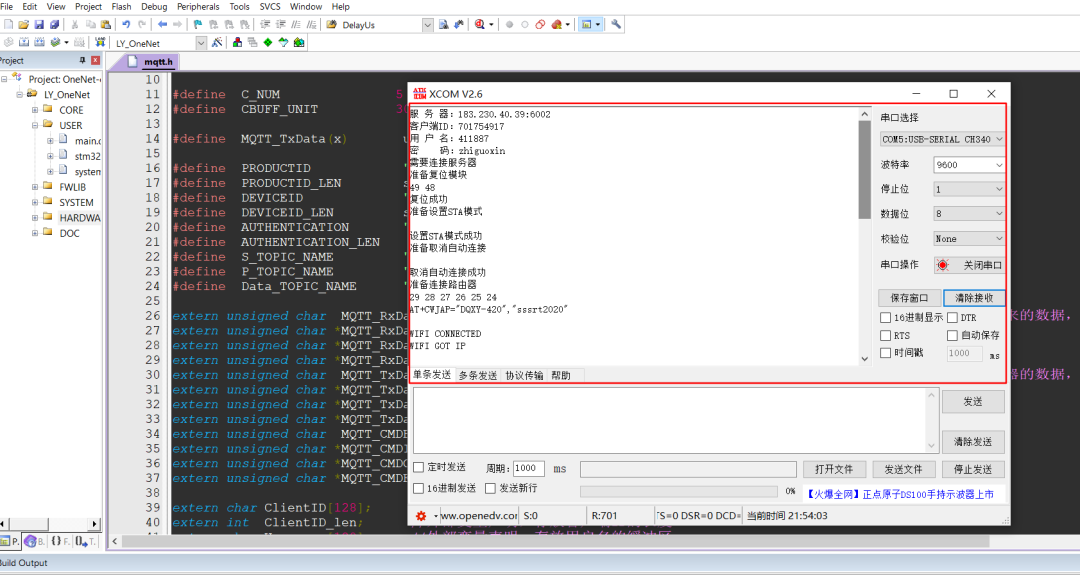
2. After a successful connection, you will find that the device is now in the online state in the background.
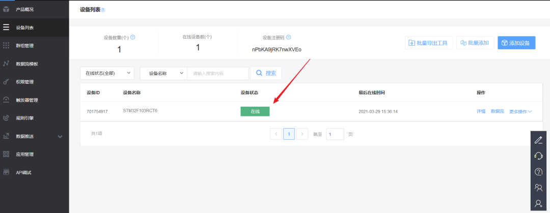
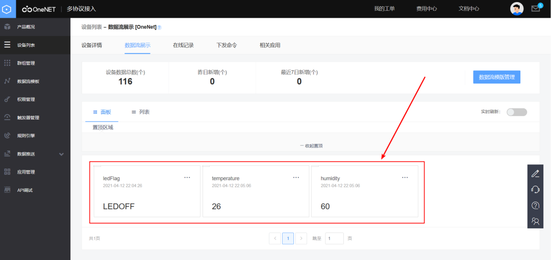
6. Data Upload Display
The temperature and humidity information from the development board is also displayed in real-time in the background.
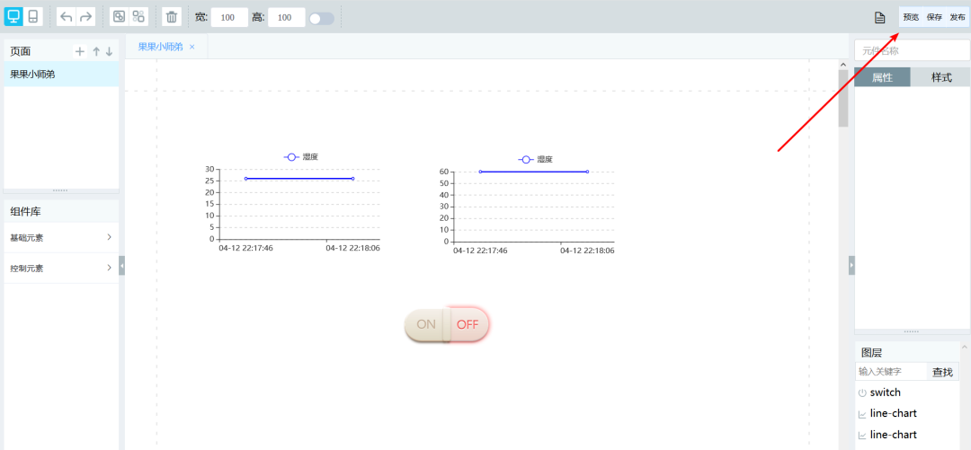
7. Create a Visualization Interface
1. Of course, we can also visualize this temperature and humidity information by following the steps below.
2. Drag the controls and modify the properties.
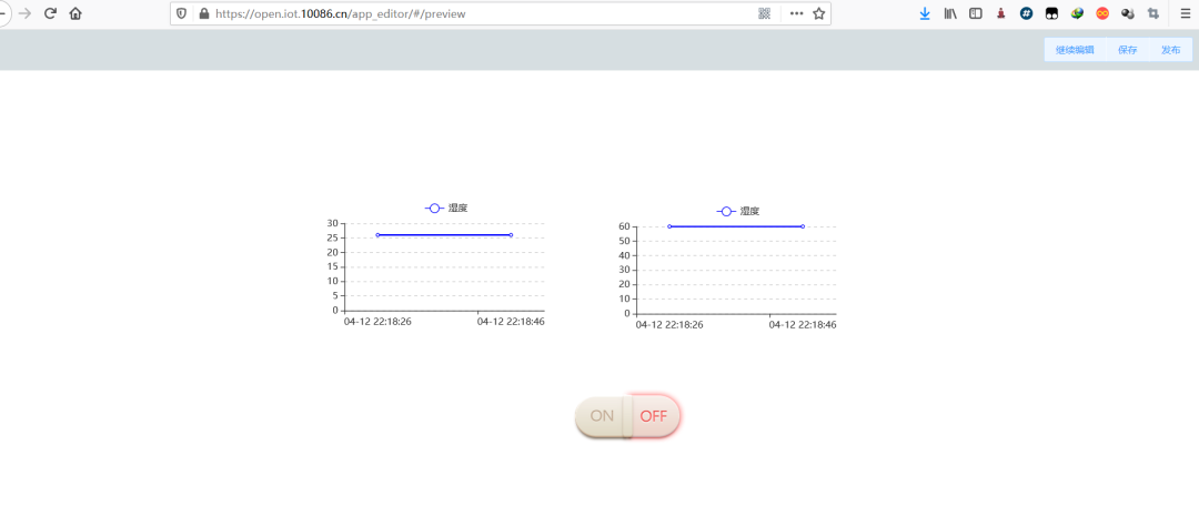
3. After editing, you can preview, save, and publish!

With that, your IoT project is complete. Download the program, and you’ve done it in just 10 minutes!