Most PLC programming consists of input contacts and output coils, which influence real-world outcomes through logical series/parallel combinations.
——————————————————
Although each model of PLC seems to have its unique programming standards, there is indeed an international standard that most PLC manufacturers at least attempt to follow. This is the IEC 61131-3 standard, which will be introduced in this chapter. Fortunately, despite the differences in programming details among different manufacturers and models of PLCs, the basic principles are largely the same. The differences between various general-purpose programming languages (such as C/C++, BASIC, FORTRAN, Pascal, Java, Ada, etc.) are far greater than the differences between the programming languages supported by different PLCs, and this fact has not prevented computer programmers from being “multilingual.” I have personally written and/or analyzed programs for over six different brands of PLCs (Allen-Bradley, Siemens, Square D, Koyo, Fanuc, Moore Products’ APACS and QUADLOG, and Modicon), most of which include multiple PLC models, and I can tell you that the differences in programming practices are mostly trivial. Once you learn how to program one model of PLC, adapting to programming for other brands and models of PLCs is quite easy. If the specific PLC you are learning to program does not fully comply with the IEC 61131-3 standard, you can still apply every principle discussed in this chapter—these fundamental concepts are indeed universal. The IEC 61131-3 standard specifies five different forms of industrial controller programming languages:
Ladder Diagram (LD)
Structured Text (ST)
Instruction List (IL)
Function Block Diagram (FBD)
Sequential Function Chart (SFC)
Not all programmable logic controllers (PLCs) support all five types of language, but almost all PLCs support Ladder Diagram (LD), which will be the main focus.
Many industrial equipment programming languages are intentionally limited in design. One reason is simplicity: any programming language that is simple enough can be understood by those without formal computer programming knowledge, but its functionality will also be limited. Another reason is safety: the more flexible and unrestricted a programming language is, the greater the likelihood of inadvertently creating complex “runtime” errors during programming. ISA safety standard 84 classifies industrial programming languages into three categories: Fixed Programming Languages (FPL), Limited Variability Languages (LVL), and Fully Variable Languages (FVL). Ladder Diagram and Function Block Diagram programming are considered “Limited Variability Languages,” while Instruction List (and traditional computer programming languages like C/C++, FORTRAN, BASIC, etc.) are considered “Fully Variable Languages,” with the potential risk of complex errors.
Relationship Between I/O States and Virtual Elements
One of the most important yet challenging concepts to grasp when learning PLC programming is the relationship between the electrical states of the PLC’s I/O points and the states of variables and other “elements” in the program. This is especially true for Ladder Diagram (LD) programming, as the program itself resembles an electrical diagram. Connecting the “real” world of switches, contactors, and other electrical devices to the “virtual” world of virtual contacts and relay “coils” in the PLC program is fundamental.
When examining a Ladder Diagram PLC program, one basic rule to remember is: each virtual contact displayed in the program will act when its corresponding bit reads a “1” state, and will be in a resting state when its corresponding bit reads a “0” state (in the PLC’s memory). If the contact is normally open (NO), it will open when its bit is 0 and close when its bit is 1. If the contact is normally closed (NC), it will close when its bit is 0 and open when its bit is 1. The 0 state keeps the contact in its “normal” (resting) state, while the 1 state drives the contact into its “abnormal” (active) state.
Another rule to remember when examining a Ladder Diagram PLC program is: the programming software provides color highlighting to show the virtual state of each program element: colored contacts are closed, while uncolored contacts are open. While the presence or absence of a “slash” symbol marks the normal state of the contact, the real-time color highlighting displayed by the PLC programming software reveals the “conducting” state of the elements.
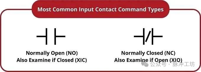
Normally Open (XIC) and Normally Closed (XIO)
The following diagram shows two types of contacts in a PLC Ladder Diagram program.
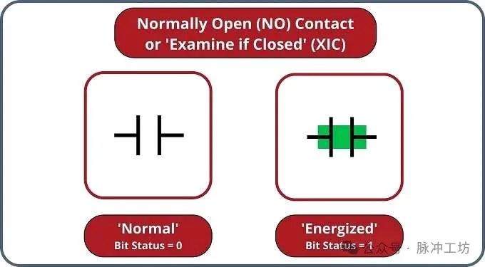
Normally open contacts will logically conduct, or “close,” when their bit state is 1, as shown in the figure. As mentioned earlier, in most Ladder Diagram programs, logically conducting or “closed” elements will be highlighted in color.
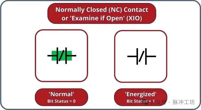
Normally closed contacts will logically conduct, or “close,” when their bit state is 0, as shown in the figure.
Just as the contacts of a pressure switch are triggered by high-pressure conditions, the contacts of a level switch are triggered by high-level conditions, and the contacts of a temperature switch are triggered by high-temperature conditions, the PLC’s virtual contacts are triggered by high bit (1) conditions. In the context of any switch, the triggered state is the opposite of its normal (resting) state.
The following simplified schematic shows a small PLC with two discrete input channels electrically activated, resulting in the states of these two bits being “1”. The color-highlighted contacts displayed in the programming editing software show the collection of contacts for various states of these input bits (highlighted = closed; unhighlighted = open). As you can see, each address pointing to a “set” bit (1) has its contact in its triggered state, while each address pointing to a “reset” bit (0) has its contact in its normal state.
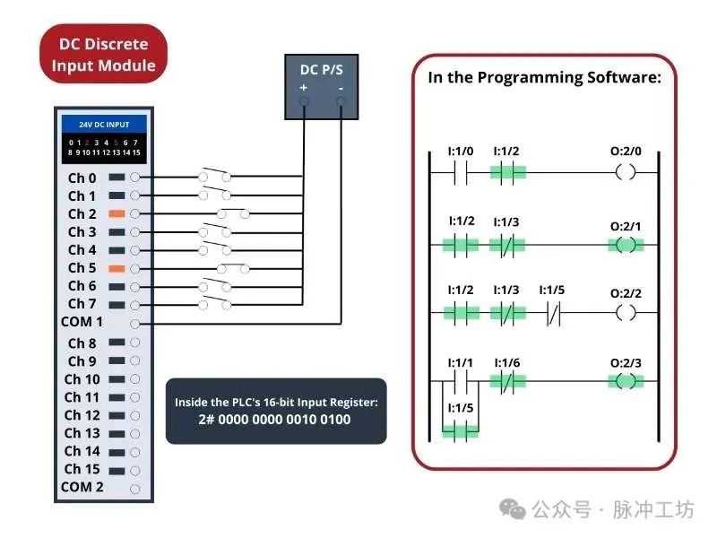
Remember, highlighted contacts are closed contacts. The contacts displayed as highlighted are either normally closed contacts with a “0” bit state or normally open contacts with a “1” bit state. It is the combination of the bit state and the contact type (normally open vs. normally closed) that determines whether the virtual contact is open (unhighlighted) or closed (highlighted) at any given time. Accordingly, it is the combination of color highlighting and virtual contact type that indicates the actual electrical activation state of a specific PLC input at any given time.
In my teaching experience, the main issue students have in understanding PLC Ladder Diagram programs is that they oversimplify and try to directly associate the real-world switches connected to the PLC with their corresponding contact instructions in the PLC program. Students mistakenly believe that the real-world switches connected to the PLC and the virtual switch contacts in the PLC program are the same thing, which is not the case. In reality, the real-world switch sends power to the PLC input, thereby affecting the state of the virtual contacts programmed into the PLC. Specifically, I have seen students frequently fall into the following misconceptions:
1. Students mistakenly believe that the contact instruction type (normally open vs. normally closed) must match the real-world switch it is associated with.
For example, students may think that if a normally open switch is used in the real world, then a normally open contact instruction must also be used in the PLC program. However, this association does not exist, as the state of the PLC’s virtual contact is determined by the bit state and contact type, not directly by the type of real-world switch.
2. Students mistakenly believe that the color highlighting of the contact instruction is equivalent to the electrical state of its associated real-world PLC input.
Color highlighting merely indicates the logical state of the virtual contact (closed or open), and does not directly reflect the actual electrical state of the PLC input. For example, a normally closed contact will be highlighted as closed when its bit state is 0, but this does not necessarily mean that the actual electrical state of the PLC input is activated.
3. Students mistakenly believe that a closed switch in the real world must lead to a closed contact instruction in the PLC program.
In reality, the state of the real-world switch affects the bit state through the PLC input, and the bit state, along with the contact type, determines the state of the virtual contact. For example, a closed real-world switch may lead to a PLC input bit state of 1, but if a normally closed contact is used in the program, that contact will actually open (unhighlighted).
Understanding these concepts is key to recognizing that the state of virtual contacts in the PLC program is determined by the bit state and contact type, rather than directly by the state of the real-world switches.
To clarify, here are some basic rules to remember when explaining contact instructions in PLC Ladder Diagram programs:
1. Each input bit in the PLC memory is “1” when its input channel is powered and “0” when its input channel is not powered.
This means that real-world switches or devices affect the state of the input bits by controlling the power to the PLC input channels.
2. Each virtual contact displayed in the program will act when its corresponding bit reads a “1” state, and will be in a resting state when its corresponding bit reads a “0” state.
The action state of the contact is determined by the state of its corresponding bit, not directly by the state of the real-world switch.
3. Highlighted contacts are closed (passing virtual power in the PLC program), while unhighlighted contacts are open (blocking virtual power in the PLC program).
Color highlighting merely indicates the logical state of the contact, not directly reflecting the actual electrical state of the PLC input.
The importance of these rules cannot be overstated when trying to understand PLC Ladder Diagram programs. The reality is a causal chain, not a direct equivalence between real-world switches and contact instruction states. Real-world switches control whether PLC input channels are powered, which in turn controls whether input register bits are “1” or “0”, which in turn controls whether contact instructions are active or resting. Thus, the virtual contacts in the PLC program are controlled by their corresponding real-world switches, rather than being as straightforwardly equivalent to real-world switches as beginners often assume.
According to these rules, we see that normally open (NO) contact instructions mimic the behavior of their real-world switches, while normally closed (NC) contact instructions behave oppositely to their real-world switches.
Color Highlighting of Activated Coils in Ladder Diagrams
In PLC Ladder Diagram programs, the color highlighting of coil instructions follows similar rules. When all contact instructions in front of a coil are closed (highlighted), the coil will be “activated” (highlighted). A highlighted coil will write “1” to its corresponding bit in memory, while an unhighlighted coil instruction will write “0” to its corresponding bit in memory. If these bits are associated with real-world discrete output channels on the PLC, their states will control the actual electrical activation of devices connected to those channels.
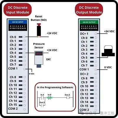
To further illustrate these basic concepts, we will examine a simple PLC system designed to activate a warning beacon when the fluid process pipeline experiences low pressure. The PLC’s task is to activate the warning light if the pressure in the process vessel drops below 270 PSI, and to keep the warning light activated even if the pressure exceeds the 270 PSI trigger point again. This way, operators will be alerted to past and current overpressure events in the process vessel.
DC control voltage (+24 volts and 0 volts) provides electrical energy for the signal potential of the input switches and the power for the warning light. Two switches are connected to this PLC’s input: a normally open push button switch as an alarm reset (pressing this switch “clears” the alarm light) and a normally open pressure switch as the sensing element for process pressure.
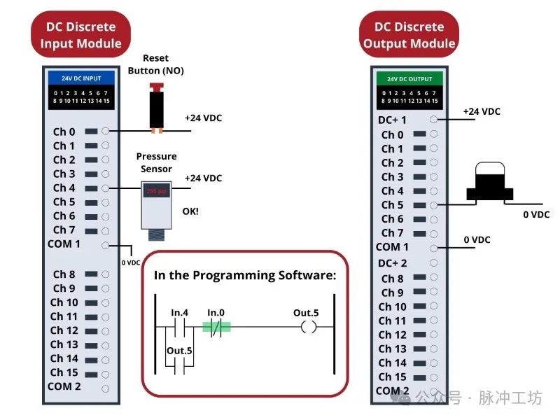
The reset button is connected to discrete input channel 0 of the PLC, while the pressure switch is connected to discrete input channel 4. The warning light is connected to discrete output channel 5. The indicator LEDs next to each I/O terminal, as well as the indicator lights on top of each module, visually display the electrical state of the I/O points, while the green shading highlights the virtual power states of the “contacts” and “coils” in the PLC program, which are displayed on the computer screen connected to the PLC via programming cable.
When no one presses the reset button, that switch will be in its normal state, which is open for a normally open switch. Similarly, when the process pressure is significantly above the 270 PSI trigger point, the pressure switch will also be in its normal state, which is open for a normally open switch. Since neither of these two switches is currently conducting, discrete input channels 0 and 4 will not be activated. This means that the “virtual” contacts in the PLC program will also be in their respective normal states. Therefore, any virtual contact drawn as normally open will be open (not passing virtual power), while any drawn as normally closed (with a diagonal line symbol) will be closed. This is why the two normally open virtual contacts In.4 and Out.5 are not highlighted, while the normally closed virtual contact In.0 is highlighted—remember, color highlighting indicates the ability to pass virtual logical power, not an indication of actual current flow through the switch.
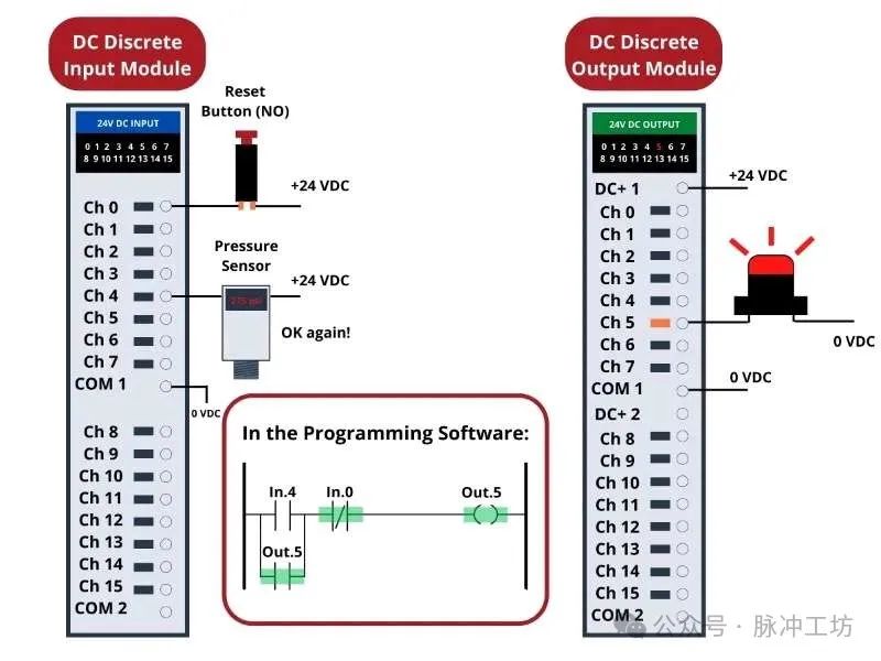
If the process vessel experiences low pressure (below 270 PSI), the pressure switch will act, closing its normally open contact. This will activate the PLC’s input channel 4, thereby “closing” the virtual contact In.4 in the Ladder Diagram program. This will send virtual power to the virtual “coil” Out.5, which will self-lock through the virtual contact Out.5 and activate the real discrete output channel 5 to light the warning light.

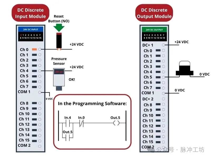
If the process pressure now rises above 270 PSI, the pressure switch will return to its normal state (open), causing the PLC’s discrete input channel 4 to lose power. However, due to the self-locking contact Out.5 in the PLC program, output channel 5 remains activated to keep the warning light on:
Thus, the Out.5 contact performs a self-locking function, maintaining the output bit of channel 5 as “1” even after the low-pressure condition disappears. This is analogous to the concept of a “self-locking” auxiliary contact in a hard-wired motor starter circuit, where the electromagnetic contactor remains activated after the “start” button switch is released.
The only way for the operator to reset the warning light is to press the reset button. This will activate the PLC’s input channel 0, thereby opening the virtual contact In.0 (normally closed), interrupting the flow of virtual power to the virtual coil Out.5, thus turning off the warning light and breaking the self-locking power in the program.
Review:
• Bits are single switch information, typically used for digital input and output devices. Bits can only take values of 1 or 0.
• Contact Instructions monitor input information, while Coil Instructions control the activation of output devices.
• When a rung of the Ladder Diagram program forms a “closed” logical path from left to right, the output coil will activate. If the logical path is interrupted (similar to a circuit interruption), the coil will deactivate.