3. Processing Axis SignalsIn the CMVM PLC program, there are multiple corresponding FB blocks for the machine tool axes, but these FB blocks are actually a single FB block with different names.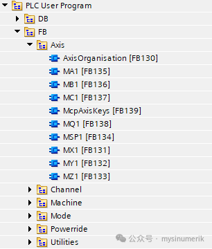 OB1 calls FB130, which in turn calls the FB block that processes each axis signal, along with FB139 (which handles the axis selection keys on the machine tool operation panel).The FB block for processing axis signals is relatively simple: it handles the controller enable, pulse enable, measurement system 1 and measurement system 2, activation magnification, return to reference point, manual jog, and axis magnification assignment.
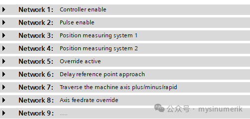 It is important to note:The difference between machine tool axes and geometric axes. Manually moving the machine tool axis corresponds to the positioning axis interface signal data blocks (DB31, DB32…), while manually moving the geometric axis corresponds to the positioning channel interface signal data block (DB21). Do not confuse them, as activating certain transformations may result in different directions for the machine tool axes and geometric axes, and the manual machine tool axis always moves as a single axis; the manual geometric axis may involve 2 or 3 axes moving together.FB139 mainly processes the axis selection and direction keys on the machine tool operation panel.
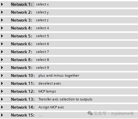 Networks 1 to 9 have the same structure.
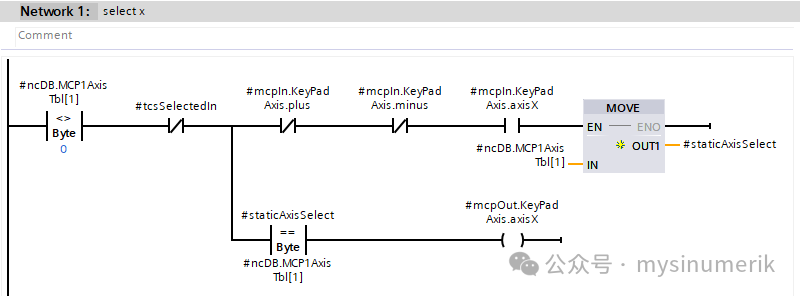 Pressing the “X” key on the panel will:
- Output the selected axis number
- Light up the LED for the “X” key
Network 10 processes the simultaneous pressing of “+” and “-” keys.Network 11 cancels the axis selection.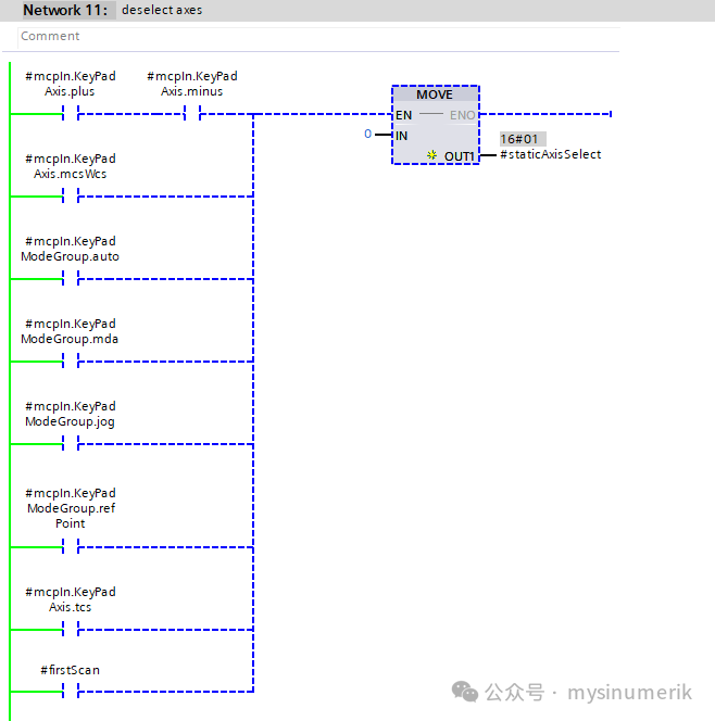 Cancel axis selection under the following conditions:
- Simultaneously press “+” and “-”
- MCS/WCS switching
- Select other working modes, such as automatic, MDA, JOG, REF
- Select TCS
- And during power-upthe first PLC scan
Network 12 processes the LED lights for the positive and negative direction keys and the rapid move key.Network 13 outputs the axis number (note that this is not the sequence number displayed on the panel).Network 14 is written using SCL, based on PLC data (the value of MD14512 sets the axis number).That’s all for now.
If you find this article useful, please share it. Thank you!