 To ensure the stability of industrial bus communication, engineers usually consider circuit solutions for lightning protection, surge protection, and overvoltage protection during the design phase. Today, we will introduce some effective bus surge protection solutions.
 The Impact of Surges on Circuits
Surges include surge current and surge voltage, which refer to the phenomenon where voltage or current exceeds normal operating levels in a circuit. In industrial communication sites, lightning overvoltage, induced lightning surges caused by lightning strikes, and surges caused by switching heavy inductive loads in power systems can lead to transient overvoltage and overcurrent. These surges can cause the data bus communication network to fail or even cause components to send incorrect signals, resulting in significant losses for users.
Table 1 Comparison of Several Types of Transient Disturbances
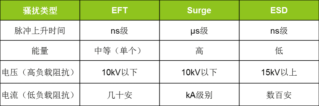
First, let’s understand a few typical transient disturbances: from the table, it can be seen that surges have the highest energy and the highest overcurrent, thus posing the greatest threat.
There are two types of surge formation:Common mode and differential mode.Surges generated during lightning or large current switching are generally common mode; differential mode surges are often caused by high voltage lines running near data cables, where poor insulation between the data cables and high voltage lines leads to stable presence in the data communication network for a longer period. The rated withstand voltage of optocouplers or magnetic couplers is common mode, that is, the withstand voltage from the front end to the back end. If this withstand voltage is exceeded, both the front and back ends may be damaged; components do not specify differential mode withstand voltage, which is determined by the circuit design. If differential mode voltage exceeds the circuit’s tolerance, the front end will be damaged while the back end may not.
Currently, there are two types of bus surge protection solutions:Using discrete components or integrated modules.
 Conventional Surge Protection Solution – Discrete Solution
Many applications require compliance with IEC61000-4-2 static discharge level 4 and IEC61000-4-5 surge immunity level 4. Generally, the ESD and surge protection levels of transceivers are relatively low, such as the isolation withstand voltage of the CTM1051M isolated CAN transceiver being 2500VDC. In bare machine conditions, both ESD and surge levels are low, so it is necessary to add peripheral circuits.
Surge protection circuits are usually divided into: isolation methods and avoidance methods.
-
Isolation Method:Using optocouplers or magnetic couplers to isolate the input and output signals, this type of isolation method can only suppress common mode surges, not differential mode surges.
-
Avoidance Method:The ground of the main device is connected together to form a single-point ground, which can safely transfer surge energy when a surge occurs. Additionally, it is necessary to add some surge suppression devices, mainly TVS diodes, varistors, and gas discharge tubes.
Combining isolation and avoidance methods can better protect the system. The avoidance devices can suppress surge protection isolation devices and also suppress differential mode surges generated on the bus. The isolation devices suppress common mode surges and protect the main device. The two complement each other, providing better protection for bus devices. Taking the CAN bus as an example, the following diagram shows the peripheral protection circuit formed by discrete components.
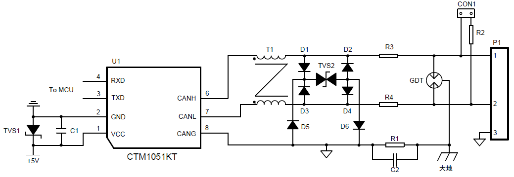
Figure 1 Recommended Protection Circuit for CAN Bus
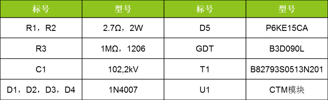
In this circuit, the GDT is placed at the front end to provide the first level of protection. When lightning strikes or surges occur, the GDT instantly reaches a low resistance state, providing a discharge path for the instantaneous large current and clamping the voltage between CAN_H and CAN_L within a range of several tens of volts. The actual values can be adjusted based on protection levels and component costs, with R3 and R4 recommended to use PTCs, and D1~D6 recommended to use fast recovery diodes. The parameter table is as follows.
Table 2 Recommended Parameter Table
 Efficient Surge Protection Solution – Module Solution
The discrete component solution, while providing effective protection, requires the introduction of many electronic components, which means the interface circuit will occupy more PCB space. If the component parameters are not chosen appropriately, it can easily cause EMC issues. Is there a more streamlined protection design? The answer is yes. One can choose to introduce the professional signal surge suppressor SP00S12, which can be used for various signal transmission systems to suppress harmful signals such as lightning strikes, surges, and overvoltage, protecting the signal ports of devices. When paired with ZLG’s fully isolated CTM or SC series isolated CAN transceivers, as shown in the following diagram, it can greatly enhance product integration while significantly shortening the development cycle.
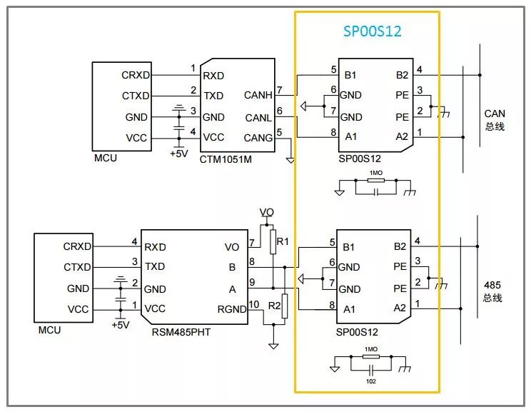
Figure 2 Module Solution
 Solution Comparison and Surge Immunity Testing
As mentioned earlier, there are two types of bus surge protection solutions. Let’s summarize:
-
Discrete component solution: more electronic components, complicated setup, occupies more PCB space, prone to EMC issues;
-
Module solution: easy to use, saves PCB space, simplifies the circuit.
Next, we will conduct surge immunity tests to verify whether the surge suppressor meets the IEC61000-4-5 ±4KV protection requirements. Taking common mode surge testing as an example, a 4KV, 1.2/50μs surge voltage is applied to the input of SP00S12, and the voltage drop at the output is tested to have been reduced to 17.1V, as shown in the waveform below.
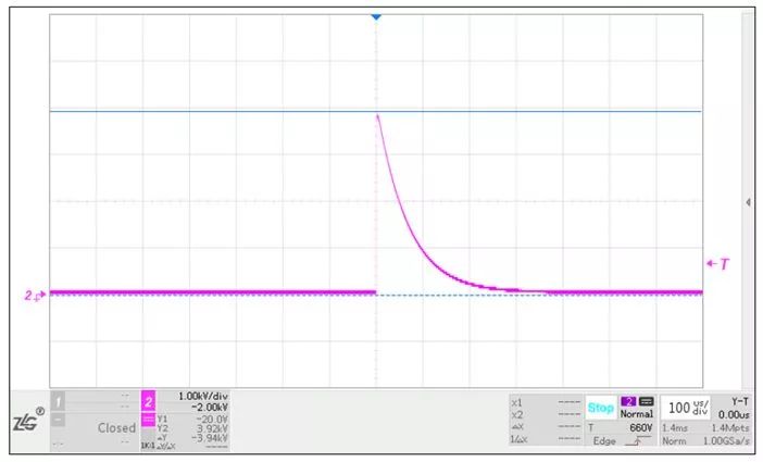
Figure 3 Input Voltage Waveform 4KV
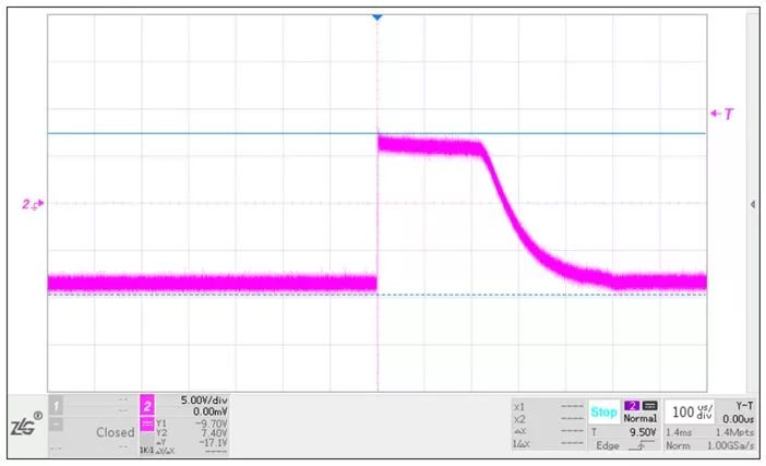
Figure 4 Output Voltage Waveform 17.1V
As can be seen, adding the SP00S12 between the transceiver and the CAN bus can easily meet the IEC61000-4-5 ±4KV surge level requirements for the CAN signal port.
Using an integrated high-surge protection isolated CAN transceiver can completely replace the combination of isolated CAN transceiver and surge suppressor, as shown in the following diagram. This solution will simplify circuit design to the maximum extent, save PCB space, and reduce product costs. It can protect against 4KV surges and 15KV electrostatic discharges while also having excellent EMC characteristics.
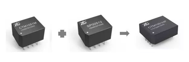
Figure 5 Integrated Isolation Solution

 If you have any questions, you can:
 Add WeChat: zlgmcu-888
 Call the official technical hotline of ZLG: 400-888-4005.