Introduction to J-Link
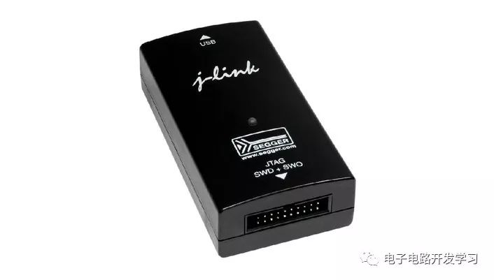
J-Link is a JTAG emulator launched by SEGGER to support emulation of ARM core chips. Simply put, it is a JTAG protocol converter.
It connects to the computer via USB, while still using the JTAG protocol to connect to the target board, completing the conversion from software to hardware.
It supports emulation for ARM7, 9, 11, Cortex-M, Cortex-A5/A8/A9 and other core chips, seamlessly integrating with IAR, Keil, and other development environments. It is easy to operate, connect, and learn, making it an excellent development tool for learning and developing ARM.
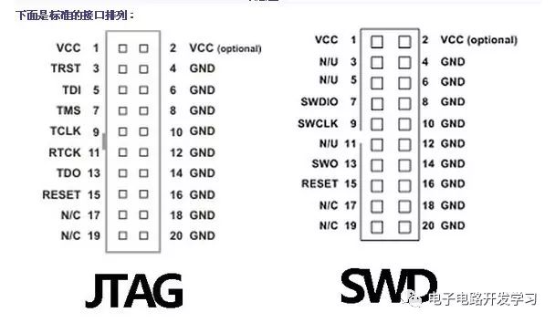
Definition of JTAG and SWD Interfaces
What is J-Scope?

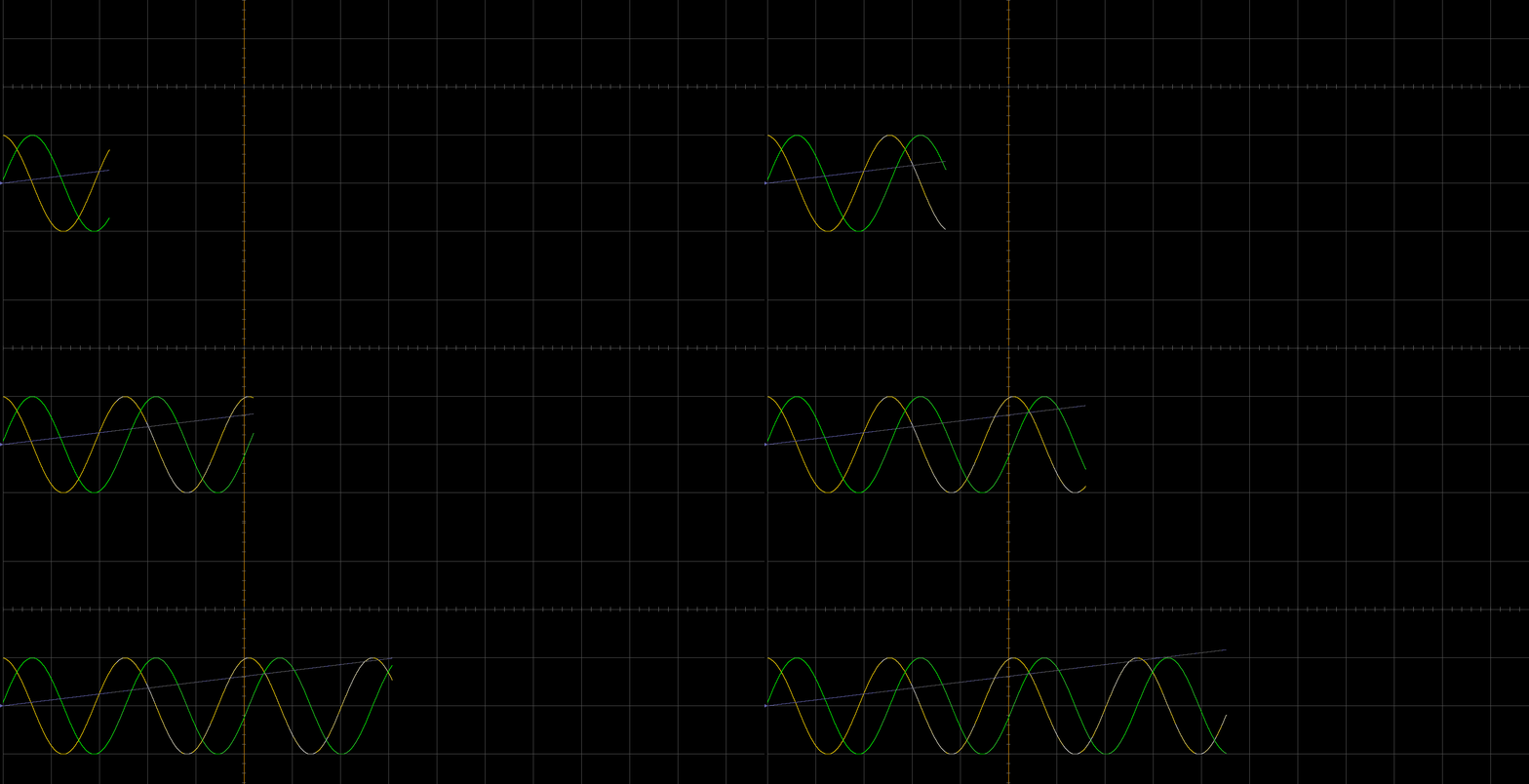
J-Scope is a software launched by SEGGER that can analyze data in real-time and display it graphically while running on the target MCU.
J-Scope can display the values of multiple variables in a manner similar to an oscilloscope. It reads ELF or AXF files and allows the selection of multiple variables for visualization.
Simply connect the target microcontroller to J-Link and start J-Scope. A few steps are needed to configure J-Scope and select the symbols to display.
The configuration can be stored in project files for easy reuse and portability, and each symbol selected in J-Scope can be configured individually.
Software Preparation
To use the J-Scope function, in addition to a JLink V9, you also need to install J-Flash and J-Scope software.
1. Download JLink_V614b.exe
Address:
http://wcc-blog.oss-cn-beijing.aliyuncs.com/img/20181014-KeilBin/JLink_Windows_V614b.exe
2. Download Setup extbackslash JScope extbackslash V611m.exe
Address:
http://wcc-blog.oss-cn-beijing.aliyuncs.com/img/20181014-KeilBin/Setup_JScope_V611m.exe
Usage Method
Write test code and download the program to the microcontroller
float x = 0;
double sin_o = 0;
double cos_o = 0;
int in;
int main(void)
{
    while(1)
    {
    x += 0.01;
    if(x >= 100)
    x = 0;
        sin_o = sin(x);
        cos_o = cos(x);
    }
}
Configuration of J-Scope Software
Create a new project
Select the corresponding microcontroller model in Target Device, and load the generated AXF file from the project
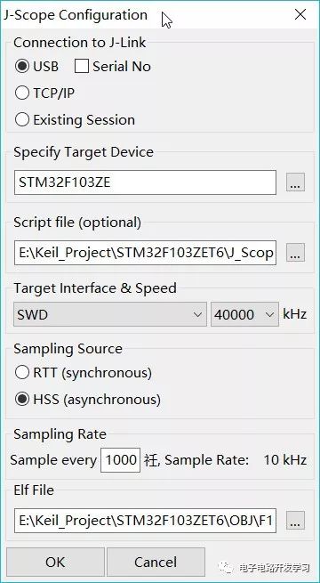
Configure as shown in the figure, click OK to complete the configuration
Right-click Add at the bottom 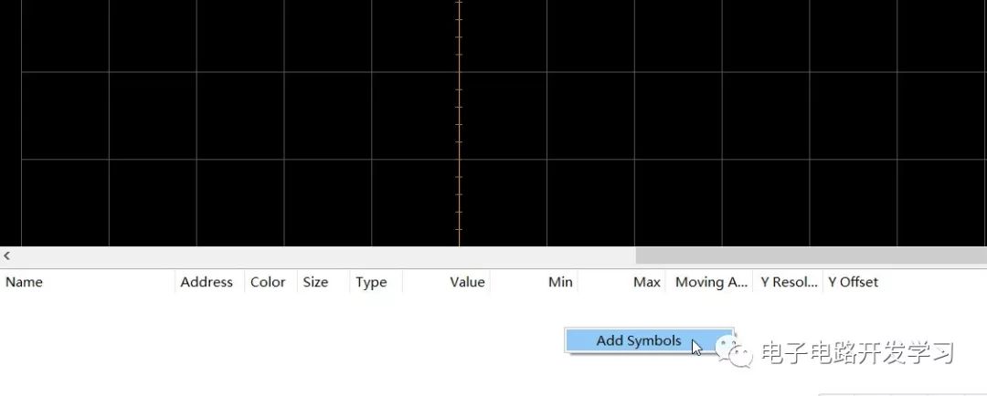
Select the variables to observe
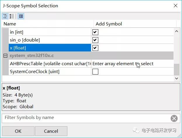
Click the red button to start running
Download the test code project
STM32F103ZET6
http://wcc-blog.oss-cn-beijing.aliyuncs.com/img/20181014-KeilBin/STM32F103ZET6.rar

This article is authorized for publication by the author “wcc149”, from the public account “Electronic Circuit Development Learning“.