Background and Overview
Sensor is an important part of the Internet of Things (IoT), “Sensors to IoT” is equivalent to “eyes to humans.” Without eyes, humans cannot see this vast world, and without sensors, IoT cannot perceive the ever-changing world.
Currently, there are many sensors developed for IoT, including Accelerometers, Magnetometers, Gyroscopes, Ambient Light Sensors, Proximity Sensors, Barometers, Humidometers, etc. Major semiconductor manufacturers around the world produce these sensors, which increases market options but also complicates application development. Different sensor manufacturers and types require their unique drivers to operate, which increases the development difficulty as applications must adapt to different sensors. To reduce application development difficulty and increase the reusability of sensor drivers, we designed the Sensor Driver Framework.
The function of the Sensor Driver Framework is to provide a unified operation interface for the upper layer, improving the reusability of upper-layer code; simplifying the difficulty of lower-level driver development, allowing sensors to be registered in the system by implementing simple ops (operations).
Overall Framework
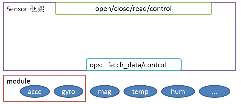
The overall architecture diagram of the Sensor Driver Framework is as follows:
 sensor
It provides a standard device interface for the upper layer <span>open/close/read/write/control</span> and a simple ops interface for the lower-level driver:<span>fetch_data/control</span>. The framework also supports modules, providing services for coupled sensor devices at the lower level.
Working Principle
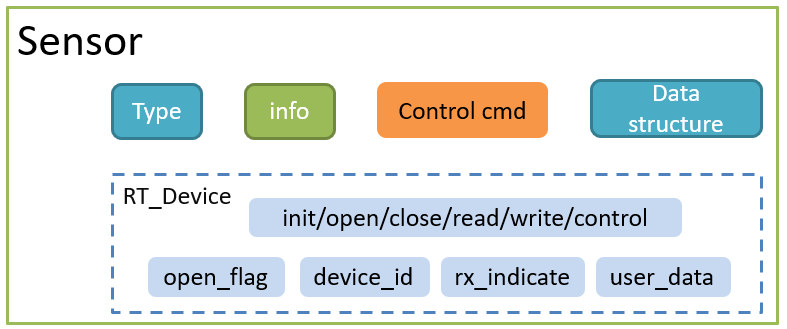
The Sensor device is actually an enhancement of the standard device <span>rt_device</span>, adding unique attributes and control commands specific to sensors, as shown in the figure below:
 sensor
The entire Sensor device consists of two parts:
-
Inherits some characteristics from the standard device, including: standard control interface,
<span>callback function</span>,<span>device_id</span>, etc. -
Unique parts of the Sensor device include:
<span>Sensor type</span>,<span>related information</span>,<span>unique control commands</span>,<span>ops</span>, and some<span>data structures</span>.
Structure of Sensor
The structure of the Sensor device is as follows:
struct rt_sensor_device
{
    struct rt_device             parent;    /* The standard device */

    struct rt_sensor_info        info;      /* The sensor info data */
    struct rt_sensor_config      config;    /* The sensor config data */

    void                        *data_buf;  /* The buf of the data received */
    rt_size_t                    data_len;  /* The size of the data received */

    const struct rt_sensor_ops  *ops;       /* The sensor ops */

    struct rt_sensor_module     *module;    /* The sensor module */
};
typedef struct rt_sensor_device *rt_sensor_t;
Sensor Information
The struct rt_sensor_info info stores information related to the Sensor itself, provided during the registration of the Sensor device, and its content should not be modified during use. The specific members are as follows:
struct rt_sensor_info
{
    rt_uint8_t     type;                    /* The sensor type */
    rt_uint8_t     vendor;                  /* Vendor of sensors */
    const char    *model;                   /* model name of sensor */
    rt_uint8_t     unit;                    /* unit of measurement */
    rt_uint8_t     intf_type;               /* Communication interface type */
    rt_int32_t     range_max;               /* maximum range of this sensor's value. unit is 'unit' */
    rt_int32_t     range_min;               /* minimum range of this sensor's value. unit is 'unit' */
    rt_uint32_t    period_min;              /* Minimum measurement period,unit:ms. zero = not a constant rate */
    rt_uint8_t     fifo_max;                /* Maximum depth of fifo  */
};
Currently, the Sensor types are limited to the following, and if new sensor types are available, a PR can be submitted to add them.
#define RT_SENSOR_CLASS_ACCE           (1)  /* Accelerometer     */
#define RT_SENSOR_CLASS_GYRO           (2)  /* Gyroscope         */
#define RT_SENSOR_CLASS_MAG            (3)  /* Magnetometer      */
#define RT_SENSOR_CLASS_TEMP           (4)  /* Temperature       */
#define RT_SENSOR_CLASS_HUMI           (5)  /* Relative Humidity */
#define RT_SENSOR_CLASS_BARO           (6)  /* Barometer         */
#define RT_SENSOR_CLASS_LIGHT          (7)  /* Ambient light     */
#define RT_SENSOR_CLASS_PROXIMITY      (8)  /* Proximity         */
#define RT_SENSOR_CLASS_HR             (9)  /* Heart Rate        */
#define RT_SENSOR_CLASS_TVOC           (10) /* TVOC Level        */
#define RT_SENSOR_CLASS_NOISE          (11) /* Noise Loudness    */
#define RT_SENSOR_CLASS_STEP           (12) /* Step sensor       */
The other members include vendor, model (e.g., “mpu6050”), unit of sensor data, communication interface type, maximum measurement range, minimum measurement range, minimum measurement period, and maximum depth of hardware FIFO.
Sensor Configuration
The Sensor Driver Framework abstracts some common configuration options, which are placed in <span>struct rt_sensor_config</span>, with the following members:
struct rt_sensor_config
{
    struct rt_sensor_intf        intf;      /* sensor interface config */
    struct rt_device_pin_mode    irq_pin;   /* Interrupt pin, The purpose of this pin is to notification read data */
    rt_uint8_t                   mode;      /* sensor work mode */
    rt_uint8_t                   power;     /* sensor power mode */
    rt_uint16_t                  odr;       /* sensor out data rate */
    rt_int32_t                   range;     /* sensor range of measurement */
};
Among these configuration items, intf and irq_pin are abstracted to decouple the sensor from the hardware. By passing the parameter <span>struct rt_sensor_config</span> during lower-level initialization, the communication interface decoupling is completed.
struct rt_sensor_intf
{
    char                       *dev_name;   /* The name of the communication device */
    rt_uint8_t                  type;       /* Communication interface type */
    void                       *user_data;  /* Private data for the sensor. ex. i2c addr,spi cs,control I/O */
};
Other configuration items are controlled by specific sensor control commands, as follows:
#define  RT_SENSOR_CTRL_GET_ID         (0)  /* Read Device ID */
#define  RT_SENSOR_CTRL_GET_INFO       (1)  /* Get Device Info */
#define  RT_SENSOR_CTRL_SET_RANGE      (2)  /* Set Sensor Measurement Range */
#define  RT_SENSOR_CTRL_SET_ODR        (3)  /* Set Sensor Data Output Rate, unit is HZ */
#define  RT_SENSOR_CTRL_SET_MODE       (4)  /* Set Work Mode */
#define  RT_SENSOR_CTRL_SET_POWER      (5)  /* Set Power Mode */
#define  RT_SENSOR_CTRL_SELF_TEST      (6)  /* Self-test */
Using these with the control interface in ops allows for sensor configuration.
Storage of Sensor Data
To facilitate data parsing, it is specified that each type of Sensor has its unique data structure, with members using <span>union</span> to reduce code size.
/* 3-axis Data Type */
struct sensor_3_axis
{
    rt_int32_t x;
    rt_int32_t y;
    rt_int32_t z;
};
struct rt_sensor_data
{
    rt_uint32_t         timestamp;          /* The timestamp when the data was received */
    rt_uint8_t          type;               /* The sensor type of the data */
    union
    {
        struct sensor_3_axis acce;          /* Accelerometer.       unit: mG          */
        struct sensor_3_axis gyro;          /* Gyroscope.           unit: mdps        */
        struct sensor_3_axis mag;           /* Magnetometer.        unit: mGauss      */
        rt_int32_t           temp;          /* Temperature.         unit: dCelsius    */
        rt_int32_t           humi;          /* Relative humidity.   unit: permillage  */
        rt_int32_t           baro;          /* Pressure.            unit: pascal (Pa) */
        rt_int32_t           light;         /* Light.               unit: lux         */
        rt_int32_t           proximity;     /* Distance.            unit: centimeters */
        rt_int32_t           hr;            /* Heat rate.           unit: HZ          */
        rt_int32_t           tvoc;          /* TVOC.                unit: permillage  */
        rt_int32_t           noise;         /* Noise Loudness.      unit: HZ          */
        rt_uint32_t          step;          /* Step sensor.         unit: 1           */
    } data;
};
Unique Ops
The ops (operation functions) include two function pointers, one for fetching sensor data (fetch_data) and the other for controlling the sensor through control commands (control).
struct rt_sensor_ops
{
    rt_size_t (*fetch_data)(struct rt_sensor_device *sensor, void *buf, rt_size_t len);
    rt_err_t (*control)(struct rt_sensor_device *sensor, int cmd, void *arg);
};
Registration Method
The sensor driver framework provides a Sensor registration function, allowing the registration of a sensor device by passing the Sensor control block, name, flag, and private data.
int rt_hw_sensor_register(rt_sensor_t sensor,
                          const char              *name,
                          rt_uint32_t              flag,
                          void                    *data);
Thus, the Sensor Driver Framework relies on the standard device framework, and as long as the sensor driver interfaces with the Sensor’s ops and calls the <span>rt_hw_sensor_register</span> function to register as a Sensor device, it can control the sensor through the standard device interface.
Module Support
The definition of module is to solve the coupling issue of two sensors at the lower level; some sensors have both accelerometer and gyroscope functionalities, and their FIFO is shared. In FIFO mode, both types of sensor data can only be read simultaneously, indicating that their data is coupled.
To address this issue, we define the module type:
struct rt_sensor_module
{
    rt_mutex_t            lock;                      /* The module lock */

    rt_sensor_t           sen[RT_SENSOR_MODULE_MAX]; /* The module contains a list of sensors */
    rt_uint8_t            sen_num;                   /* Number of sensors contained in the module */
};
This contains pointers to the control blocks of coupled sensor devices, allowing simultaneous updates of the accelerometer value while reading the gyroscope data, thus resolving the coupling issue at the lower level.
Previous Recommendations:
1. 50 Million Yuan Funding for Major Chip Technology Projects, RT-Thread Assessment Indicators
2. Promoting Efficient Development of IoT, RT-Thread Launches IoT Sensor Logo Program
3. RT-Thread Learning Notes for Community Newcomers — Thread Management
4. RT-Thread Learning Notes for Community Newcomers 2 — Clock Management
5. Xiong Puxiang: 2019, Go RT-Thread!

Join the RT-Thread Sensor Technology Group
From now on, add Xiao Shimei (WeChat: RT-Thread2006) with the note “Name + Company”. After passing the review, you can join the “Sensor Professional Technology Group”. Joining the group allows you to:
a. Receive support for sensor driver development-related queries from the RT-Thread official team
b. Get early access to sensor driver development materials/tutorials, and have the opportunity to participate in sensor-related activities
c. Meet more partners in the sensor industry, directly communicate with industry leaders, and build connections
d. Enjoy occasional RT-Thread community benefits waiting for you~

When adding friends, please note “Name + Company”

RT-Thread
Make the development of IoT terminals simple and fast, maximizing the value of chips.Apache2.0 protocol, can be used for free in commercial products without the need to disclose source code, no potential commercial risk.
Long press the QR code to follow us
 Click “Read Original” to enter the RT-Thread Sensor Logo Program!
