Skip to content
The automotive bus we are most familiar with is CAN, while LIN and FlexRay may be somewhat unfamiliar to many. Next, let’s introduce these four types of automotive buses.
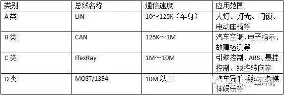
The automotive bus is the communication network that connects the lower-level automotive devices or instruments within the vehicle.Currently, there are four mainstream automotive buses: CAN bus, LIN bus, FlexRay bus, and MOST bus.
A table is used to illustrate the differences among various buses.
1. The Birth of Automotive Bus
The birth of automotive bus is inseparable from the development of automotive electronics. The degree of automotive electronicization is also regarded as an important indicator of the level of modern vehicles. Traditional automotive electronics mostly use point-to-point single communication methods with little interconnection, which inevitably leads to a massive wiring system. According to statistics, a high-end car using traditional wiring methods can have a wire length of up to 2000 meters and about 1500 electrical nodes, and this number approximately doubles every 10 years.
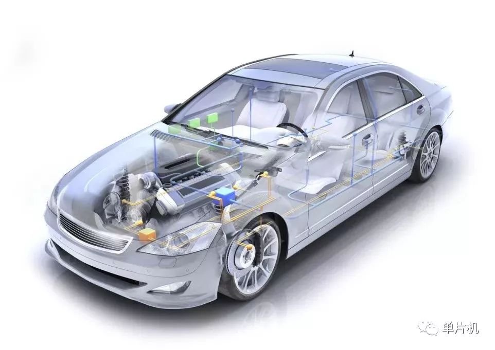
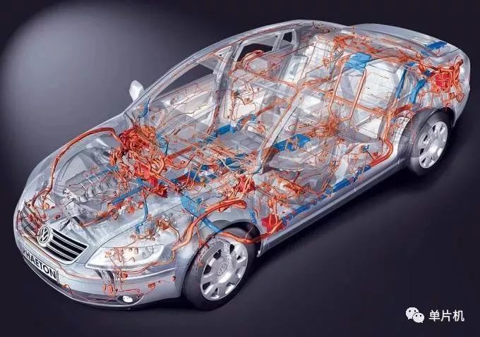 This further exacerbates the conflict between bulky wiring harnesses and the limited available space in vehicles. From both material cost and work efficiency perspectives, traditional wiring methods cannot adapt to the development of modern automobiles. Additionally, to meet the real-time requirements of various electronic systems, public data from the vehicle (such as engine speed, wheel speed, throttle pedal position, etc.) must be shared, and the real-time requirements of each control unit vary. Therefore, traditional electrical networks can no longer adapt to the development of modern automotive electronic systems, leading to the emergence of new automotive bus technologies.
 The CAN bus, also known as the automotive bus, stands for “Controller Area Network” and is a serial communication network that effectively supports distributed control and real-time control. It connects various single control units in some form (mostly star-shaped) to form a complete system.
The CAN bus was originally developed by Bosch in Germany to solve the data exchange between numerous electronic control units (ECUs) in modern vehicles. It is now widely used in automotive electronic systems and has become the main industry standard in European automotive manufacturing, representing the mainstream development trend of automotive electronic control networks.
The CAN bus, also known as the automotive bus, stands for “Controller Area Network” and is a serial communication network that effectively supports distributed control and real-time control. It connects various single control units in some form (mostly star-shaped) to form a complete system.
The CAN bus was originally developed by Bosch in Germany to solve the data exchange between numerous electronic control units (ECUs) in modern vehicles. It is now widely used in automotive electronic systems and has become the main industry standard in European automotive manufacturing, representing the mainstream development trend of automotive electronic control networks.
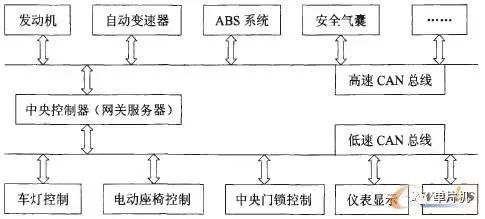 Many well-known automotive manufacturers around the world, such as Volkswagen, Benz, BMW, Porsche, and Rolls-Royce, have adopted the CAN bus for data communication within automotive control systems.
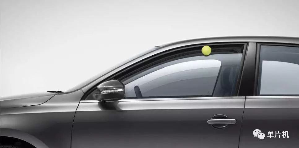
LIN is a new type of low-cost open serial communication protocol jointly launched by Motorola and Audi, mainly used for in-vehicle distributed electronic control systems, especially for digital communication scenarios aimed at intelligent sensors or actuators. It is primarily used for controlling electric windows, seat adjustments, lighting, etc.
A typical LIN network can have up to 12 nodes. For example, in the case of window control, there are door locks, window glass switches, window lift motors, and operation buttons on the car door, all of which can be connected with just one LIN network. Through a CAN gateway, the LIN network can also exchange information with other systems in the vehicle to achieve richer functionalities. LIN has now become an international standard accepted by most automotive manufacturers and parts producers.
The cost savings of LIN compared to CAN mainly come from the use of single-wire transmission, low implementation costs of hardware or software in silicon chips, and the absence of quartz or ceramic oscillators in subordinate nodes. These advantages come at the expense of lower bandwidth and limited single-master bus access methods.
LIN consists of one master node and one or more slave nodes. All nodes contain a subordinate communication task that is divided into sending and receiving tasks, while the master node also contains an additional master sending task. In real-time LIN, communication is always initiated by the master task.
Many well-known automotive manufacturers around the world, such as Volkswagen, Benz, BMW, Porsche, and Rolls-Royce, have adopted the CAN bus for data communication within automotive control systems.
LIN is a new type of low-cost open serial communication protocol jointly launched by Motorola and Audi, mainly used for in-vehicle distributed electronic control systems, especially for digital communication scenarios aimed at intelligent sensors or actuators. It is primarily used for controlling electric windows, seat adjustments, lighting, etc.
A typical LIN network can have up to 12 nodes. For example, in the case of window control, there are door locks, window glass switches, window lift motors, and operation buttons on the car door, all of which can be connected with just one LIN network. Through a CAN gateway, the LIN network can also exchange information with other systems in the vehicle to achieve richer functionalities. LIN has now become an international standard accepted by most automotive manufacturers and parts producers.
The cost savings of LIN compared to CAN mainly come from the use of single-wire transmission, low implementation costs of hardware or software in silicon chips, and the absence of quartz or ceramic oscillators in subordinate nodes. These advantages come at the expense of lower bandwidth and limited single-master bus access methods.
LIN consists of one master node and one or more slave nodes. All nodes contain a subordinate communication task that is divided into sending and receiving tasks, while the master node also contains an additional master sending task. In real-time LIN, communication is always initiated by the master task.
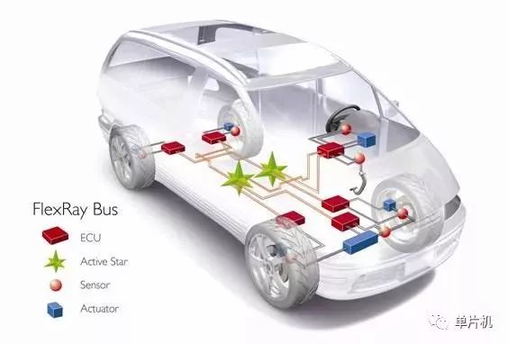
 FlexRay bus is a new communication standard jointly developed by BMW, Philips, Freescale, and Bosch, specifically designed for in-vehicle networking. It adopts a time-triggered mechanism and features high bandwidth and good fault tolerance, offering certain advantages in terms of real-time performance, reliability, and flexibility.
FlexRay is a high-speed, deterministic bus technology for automobiles that possesses fault tolerance capabilities. It combines event-triggered and time-triggered methods, achieving efficient network utilization and system flexibility, and can serve as the backbone of the next generation of in-vehicle networks.
FlexRay can be applied in passive bus and star network topologies, as well as in combinations of both. Both topologies support dual-channel ECUs, which integrate multiple system-level functions to save production costs and reduce complexity. The dual-channel architecture provides redundancy and doubles the available bandwidth, with a maximum data transmission rate of 10 Mbps for each channel. Currently, FlexRay is mainly used in safety-related drive-by-wire systems and power systems, and has been applied in BMW’s high-end vehicles.
BMW first applied FlexRay technology in the electronic control shock absorber system of the 2007 X5 series. This vehicle uses Freescale-based microcontrollers and NXP transceivers to monitor data regarding vehicle speed, longitudinal and lateral acceleration, steering angle, body and tire acceleration, and ride height, achieving better ride comfort and safety during driving, as well as high-speed responsiveness. Additionally, it minimizes load variations applied to the tires and vibrations of the chassis.
FlexRay bus is a new communication standard jointly developed by BMW, Philips, Freescale, and Bosch, specifically designed for in-vehicle networking. It adopts a time-triggered mechanism and features high bandwidth and good fault tolerance, offering certain advantages in terms of real-time performance, reliability, and flexibility.
FlexRay is a high-speed, deterministic bus technology for automobiles that possesses fault tolerance capabilities. It combines event-triggered and time-triggered methods, achieving efficient network utilization and system flexibility, and can serve as the backbone of the next generation of in-vehicle networks.
FlexRay can be applied in passive bus and star network topologies, as well as in combinations of both. Both topologies support dual-channel ECUs, which integrate multiple system-level functions to save production costs and reduce complexity. The dual-channel architecture provides redundancy and doubles the available bandwidth, with a maximum data transmission rate of 10 Mbps for each channel. Currently, FlexRay is mainly used in safety-related drive-by-wire systems and power systems, and has been applied in BMW’s high-end vehicles.
BMW first applied FlexRay technology in the electronic control shock absorber system of the 2007 X5 series. This vehicle uses Freescale-based microcontrollers and NXP transceivers to monitor data regarding vehicle speed, longitudinal and lateral acceleration, steering angle, body and tire acceleration, and ride height, achieving better ride comfort and safety during driving, as well as high-speed responsiveness. Additionally, it minimizes load variations applied to the tires and vibrations of the chassis.
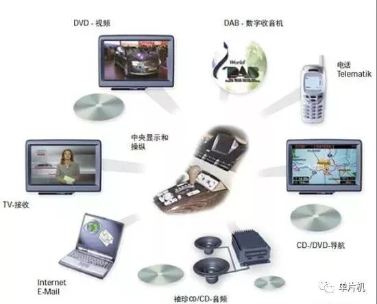
 MOST is a data bus technology developed specifically for in-vehicle use, serving multimedia applications. MOST stands for “Media Oriented Systems Transport”.
Since the BMW 7 series first adopted MOST (Media Oriented Systems Transport) technology, the popularity of this technology has surged in recent years, enabling real-time transmission of audio and video to meet the demands of high-end automotive entertainment systems; it can be used in in-vehicle cameras and other driving systems.
Characteristics of MOST bus:
(1) Achieves a data transmission speed of 24.8 Mbit/s under low-cost conditions.
(2) Can operate regardless of whether there is a master control computer.
(3) Supports real-time processing of audio and compressed images.
(4) Supports synchronous and asynchronous data transmission.
(5) The transceivers are embedded with a virtual network management system.
(6) Supports various network connection methods, providing a MOST device standard for convenient and simple application system interfaces.
(7) By adopting MOST, not only can the weight of the wiring harness connecting various components be reduced, and noise minimized, but it can also alleviate the burden on system development technicians, ultimately achieving centralized control of various devices for users.
(8) The optical fiber network is not affected by electromagnetic radiation interference and ground loops.
MOST is a data bus technology developed specifically for in-vehicle use, serving multimedia applications. MOST stands for “Media Oriented Systems Transport”.
Since the BMW 7 series first adopted MOST (Media Oriented Systems Transport) technology, the popularity of this technology has surged in recent years, enabling real-time transmission of audio and video to meet the demands of high-end automotive entertainment systems; it can be used in in-vehicle cameras and other driving systems.
Characteristics of MOST bus:
(1) Achieves a data transmission speed of 24.8 Mbit/s under low-cost conditions.
(2) Can operate regardless of whether there is a master control computer.
(3) Supports real-time processing of audio and compressed images.
(4) Supports synchronous and asynchronous data transmission.
(5) The transceivers are embedded with a virtual network management system.
(6) Supports various network connection methods, providing a MOST device standard for convenient and simple application system interfaces.
(7) By adopting MOST, not only can the weight of the wiring harness connecting various components be reduced, and noise minimized, but it can also alleviate the burden on system development technicians, ultimately achieving centralized control of various devices for users.
(8) The optical fiber network is not affected by electromagnetic radiation interference and ground loops.
The MOST bus network connects various control units through a ring data bus, which transmits data in only one direction, meaning each control unit always has two optical fibers, one for transmission and the other for reception.
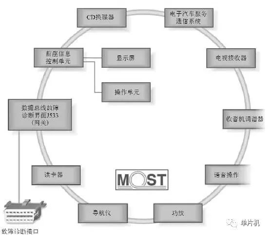
The MOST bus adopts a ring network structure.
Optical fiber connector: The optical fiber connects to the control unit using a specialized optical connector. An arrow on the connector indicates the signal direction (to the receiver) for the input end, while the connector housing forms the connection with the control unit. The optical signal is transmitted to the control unit or to the next bus user through the optical fiber conductor and optical connector.
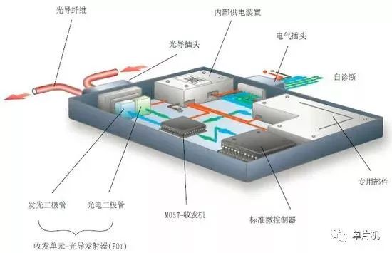
Diagram of MOST bus control unit structure.
Control unit power module: The electricity supplied through the electrical connector is then distributed to various components by the internal power supply device, allowing for the independent shutdown of a specific component within the control unit, thereby reducing static current.
Transceiver optical transmitter (FOT): This device consists of a photodiode and a light-emitting diode. The incoming optical signal is converted into a voltage signal by the photodiode and sent to the MOST transceiver.
MOST transceiver: The MOST transceiver consists of a transmitter and a receiver.
Control unit (ECU): The control unit (ECU) contains a microprocessor for controlling all basic functions of the control unit.
Specialized components: These components are used to control certain specialized functions, such as CD players and radio tuners.
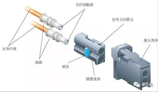
Diagram of MOST bus optical fiber pull line.
The MOST bus transmits data using optical pulses. The MOST bus adopts a ring structure. Data can only be transmitted in one direction within the ring bus.
The transmission technology of MOST is similar to that of the Public Switched Telephone Network (PSTN), with defined designs for data channels and control channels. The control channel is used to set how to use and transmit data through the data channel. Once set, the data continues to flow from the sender to the receiver without further packet processing, making it ideally suited for real-time audio and video streaming transmission.
MOST fully complies with the ISO/OSI 7-layer data communication protocol reference model, and in terms of network connections, MOST adopts a ring topology. However, for more stringent requirements in control applications, MOST also allows for star (also known as radial) or dual-ring connection configurations. Furthermore, each MOST control network allows for a maximum of 64 devices (nodes) to be connected.
(The content of this issue comes from the internet, and the copyright belongs to the original author)
-
Repair process for CAN bus short circuit faults
-
Common faults of CAN bus and multimeter repair methods
-
Which automotive computers are prone to failure, and how to repair computer chips?
-
117-page PPT detailing automotive CAN data bus, not to be missed!
-
[Case Analysis] Automotive LIN bus technology case analysis
-
[Case Analysis] Car won’t start after sitting overnight, starter also won’t work
-
Key components of the CAN bus system and solutions for technical faults
-
Common faults and diagnostic methods for FlexRay bus systems
Click on the “Read the original text” below to recharge together!
I appreciate your likes and shares!