Click on the above “Embedded Miscellaneous“, select “Pin to Top” to view programming notes at the first opportunity!
Introduction to UART
The STM32 chip has multiple USART peripherals for serial communication, which stands for Universal Synchronous Asynchronous Receiver and Transmitter. It can flexibly perform full-duplex data exchange with external devices.
Unlike USART, it also has a UART peripheral (Universal Asynchronous Receiver and Transmitter), which is a stripped-down version of USART that only supports asynchronous communication.
A simple way to differentiate between synchronous and asynchronous communication is to check whether a clock output is provided externally during communication. The serial communication we commonly use is basically UART.
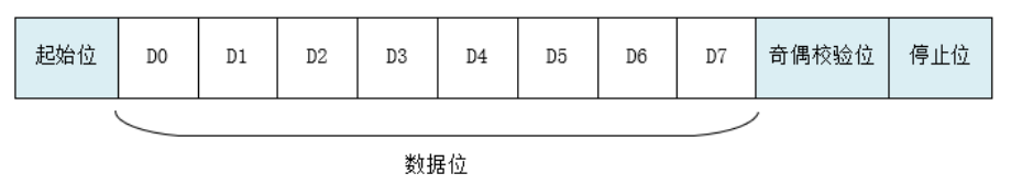
As an asynchronous serial communication protocol, UART works by transmitting each character of the data one bit at a time.
The data transmission format is as follows:
UART Device Framework Study Notes
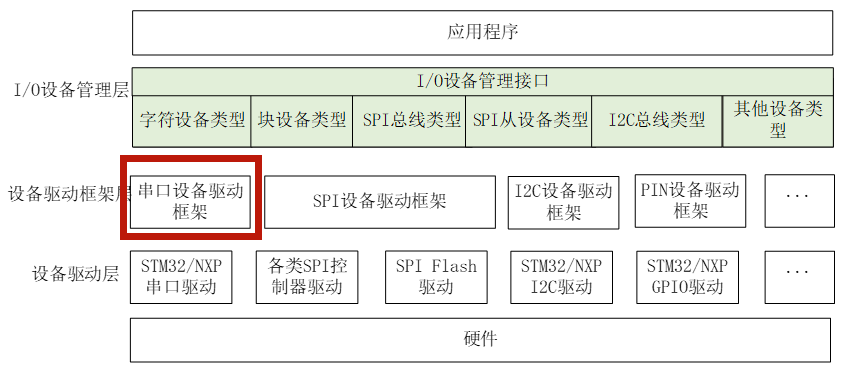
RT-Thread provides a simple I/O device model framework that lies between the hardware and the application, divided into three layers from top to bottom: I/O device management layer, device driver framework layer, and device driver layer:
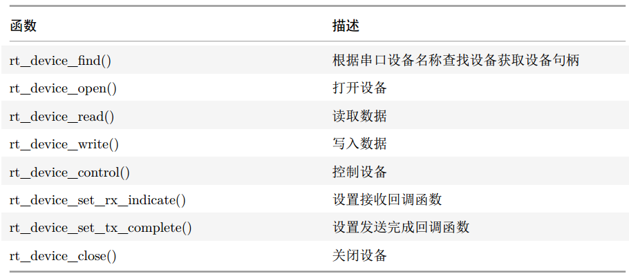
The application program accesses the serial device interface:
Now let’s look at an example:
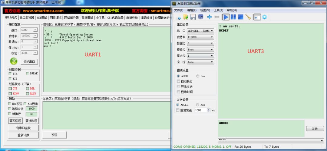
Using two serial ports (uart1 and uart3), uart1 serves as the system’s debugging serial port for printing some log information, while uart3 is the test serial port for this experiment, implementing send and receive tests with the serial debugging assistant.
After the uart3 device starts, it sends the string I am uart3 to the serial debugging assistant. Meanwhile, uart3 receives data using interrupts and outputs the data in a staggered manner; for instance, if it receives the ASCII character A, it will reply with B.
#define SAMPLE_UART_NAME "uart3" /* Serial device name */
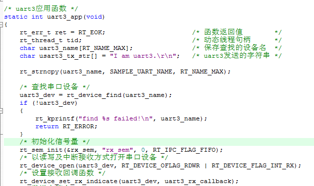
/* uart3 application function */
static int uart3_app(void)
{
rt_err_t ret = RT_EOK; /* Function return value */
rt_thread_t tid; /* Dynamic thread handle */
char uart3_name[RT_NAME_MAX]; /* Save the device name for lookup */
char usart3_tx_str[] = "I am uart3.\r\n"; /* String sent by uart3 */
rt_strncpy(uart3_name, SAMPLE_UART_NAME, RT_NAME_MAX);
/* Find serial device */
uart3_dev = rt_device_find(uart3_name);
if (!uart3_dev)
{
rt_kprintf("find %s failed!\n", uart3_name);
return RT_ERROR;
}
/* Initialize semaphore */
rt_sem_init(&rx_sem, "rx_sem", 0, RT_IPC_FLAG_FIFO);
/* Open serial device in read/write and interrupt receive mode */
rt_device_open(uart3_dev, RT_DEVICE_OFLAG_RDWR | RT_DEVICE_FLAG_INT_RX);
/* Set receive callback function */
rt_device_set_rx_indicate(uart3_dev, uart3_rx_callback);
/* Send string */
rt_device_write(uart3_dev, 0, usart3_tx_str, (sizeof(usart3_tx_str) - 1));
/* Create dynamic thread: priority 25, time slice 5 system ticks, thread stack 512 bytes */
tid = rt_thread_create("uart3_rx_thread",
static_uart3_rx_entry,
RT_NULL,
STACK_SIZE,
THREAD_PRIORITY,
TIMESLICE);
/* Start dynamic thread if created successfully */
if (tid != RT_NULL)
{
rt_thread_startup(tid);
}
return ret;
}
Our application program first looks up the device by the serial device name uart3, and after finding the device, it returns the serial device handle uart3_dev.
Why can the application program find the serial device named uart3? This is because our hardware driver layer has already registered the serial device named uart3 in the system:
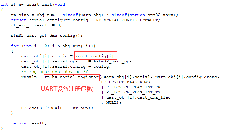
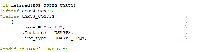
The serial device registration function will call the generic device registration function:
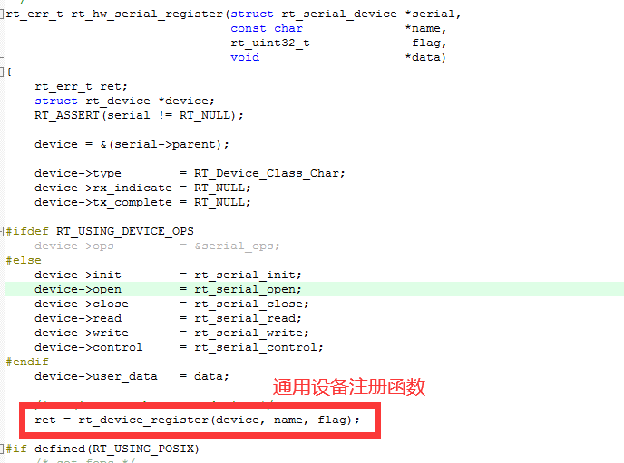
This process involves the following functions:
-
uart3_app function: defined in main.c. -
rt_hw_usart_init function: defined in drv_usart.c. -
rt_hw_serial_register function: defined in serial.c. -
rt_device_register function: defined in device.c. -
rt_device_find function: defined in device.c.
In the RT-Thread driver framework block diagram above, it is divided into several layers, with the corresponding relationships as follows:
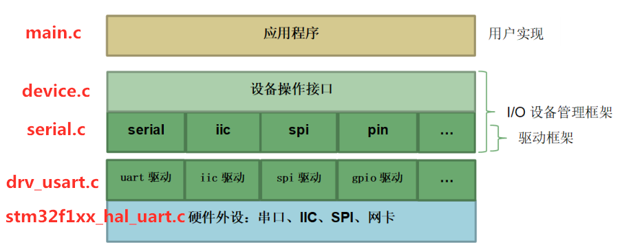
Here, the main.c file belongs to the application layer, and our application program is:
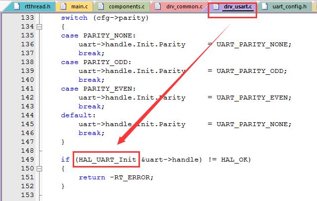
The drv_usart.c file belongs to the hardware device driver layer, which is provided by RT-Thread and is part of the board support package:
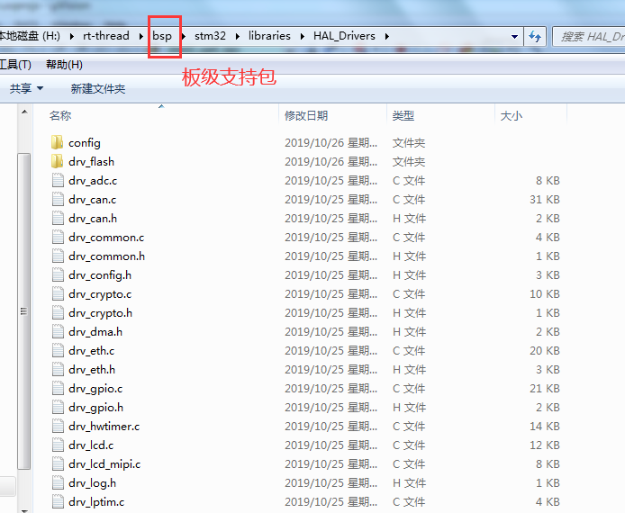
This layer is hardware-related and calls the underlying chip firmware library, such as:
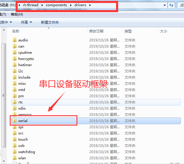
The serial.c file belongs to the driver framework (driver abstraction layer), which is a component of the RT-Thread system:
Its position in the RT-Thread source code is as follows:
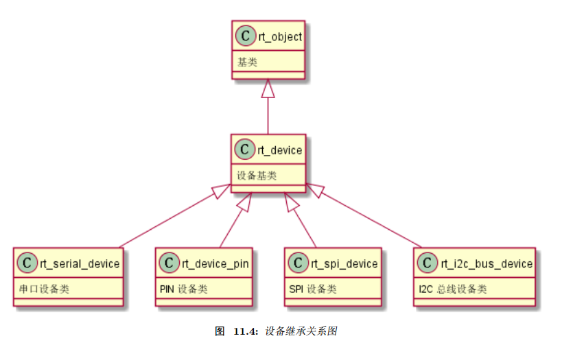
The device.c file provides the application program with interfaces for operating devices, and this file belongs to the RT-Thread kernel files. The RT-Thread kernel is designed with an object-oriented design philosophy, where devices belong to a category of objects. The inheritance relationship is as follows:
In this application program, we use semaphores (other synchronization mechanisms can also be used, such as events). Semaphores belong to one of the IPC mechanisms:

Semaphores are used for synchronization between threads and interrupts, and in our experiment, it is the synchronization between interrupts and threads.
In bare metal development, there is a scenario (interrupt receiving data, handling data in the main function):
In the serial reception interrupt function, data is received, and a global variable is used as an interrupt reception flag. When an interrupt is triggered, this flag variable is set; on the other hand, in the while loop of our main function, we check whether this flag has been set. If set, we perform the corresponding operation and reset the flag variable.
In the RT-Thread system, its IPC mechanism does similar things to what the flag variable does in the bare metal development (interrupt and thread synchronization). For example, in our experiment, if the receive interrupt of uart3 is triggered, it will trigger a callback function, such as:
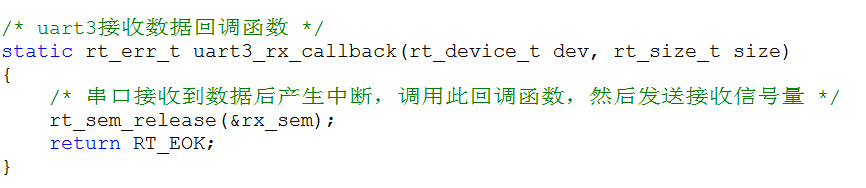
In the callback function, the semaphore release operation is performed, and the thread blocks waiting for the reception semaphore:
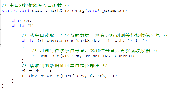
After receiving the data, it sends the data in a staggered manner. Finally, our experimental results are as follows:
That concludes this note sharing. If there are any errors, please feel free to point them out. Thank you!
Conclusion
If you find the article good, sharing and liking is also our motivation to keep updating.
You May Also Like:
Using ARM Cortex-M Series MCU Error Code Auto-Trace Library
Experience with RT-Thread Studio: Truly Impressive!
[RT-Thread Notes] Partition Management for FLASH
[RT-Thread Notes] Critical Section Issues and IPC Mechanisms
Do You Really Know Serial Communication? Check Out These Experiences
Reply 【1024】 in the WeChat public account chat interface to get a free miscellaneous data package, including but not limited to: C/C++, Python, Linux, microcontrollers, FPGA, etc.