Author | Acuity
1. Introduction
The I2C bus is a simple, “bidirectional two-wire synchronous serial bus” developed by PHILIPS. The use of I2C is not unfamiliar; C51, ARM, MSP430, etc., generally integrate hardware I2C, or for those that do not integrate I2C, it is possible to simulate an I2C bus using ordinary IO ports based on the bus timing diagram.
For the widely criticized hardware I2C in STM32, many people use simulated I2C. There are many source codes for simulated I2C, most of which are quite similar. The simulated I2C provided in various examples seems not very standardized (personal opinion), especially when multiple peripherals are connected to one I2C bus, simulating multiple I2C buses, or when replacing an I2C peripheral, significant modifications to the source code, copying the source code, and re-tuning the timing are required.
After reading the Linux device driver framework and the RT-Thread driver framework, it was found that handling it at the bus layer is particularly good, perfectly solving the aforementioned issues. This article organizes and modifies the simulated I2C for use on bare metal based on RT-Thread and Linux.
2. Linux and RT-Thread Device Driver Model
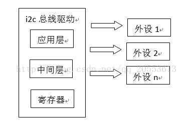
3. Bare Metal I2C Bus Abstraction on MCU
The implementation source code for this part is: i2c_core.c i2c_core.h
1) I2C Bus Abstraction External Interface (API)
“i2c_bus_xfer” is the API encapsulation for I2C, with the function prototype as follows, providing a function model that needs to instantiate the function pointer.
int i2c_bus_xfer(struct i2c_dev_device *dev, struct i2c_dev_message msgs[], unsigned int num)
{
 int size;
 size = dev->xfer(dev, msgs, num);
 return size;
}
a) This function serves as the external interface for driving peripherals, with all operations performed through this function interface, separating it from the underlying bus implementation, such as EEPROM, RTC, temperature sensors, etc.;
b) One external function has been implemented for 90% of cases, with special cases to be improved or added later.
c) struct i2c_dev_device *i2c_dev
2) I2C Bus Abstraction API Parameters
a) i2c_dev: I2C device pointer, of type “struct i2c_dev_device”; when driving an I2C peripheral, this pointer device must be initialized first;
b) msgs: A frame of I2C data, a buffer for sending data and storing returned data;
c) num: Number of data frames.
3) struct i2c_dev_device
This structure is critical; when calling the API to drive peripherals, it must be initialized first (similar to registering devices in Linux/RT-Thread). The complete device includes two parts: data operation functions and I2C-related information (such as hardware I2C or simulated I2C). Therefore, the prototype of “struct i2c_dev_device” is:
struct i2c_dev_device
{
 int (*xfer)(struct i2c_dev_device *dev, struct i2c_dev_message msgs[], unsigned int num);
 void *i2c_phy;
};
a) The first parameter is a function pointer for data transmission and reception, called through this function pointer to implement the actual function;
b) The second parameter is a void pointer, initialized to point to the physical I2C we use (hardware/simulated), which can be forcibly converted to the corresponding type during use.
4) xfer
This function has the same parameters as the I2C bus device external interface function “i2c_bus_xfer”; refer to the parameters in point 2 of this section for initialization.
5) struct i2c_dev_message
“struct i2c_dev_message” contains a frame of data information for accessing the I2C peripheral, including sending data, peripheral slave address, access identifiers, etc. The prototype is as follows:
struct i2c_dev_message
{
 unsigned short addr;
 unsigned short flags;
 unsigned short size;
 unsigned char *buff;
 unsigned char retries;
};
a) addr: The I2C peripheral slave address, commonly 7 bits, 10 bits are used less frequently;
b) flags: Identifiers for sending, receiving, acknowledging, address bit selection, etc.; several identifiers are as follows:
#define I2C_BUS_WR 0x0000
#define I2C_BUS_RD (1u << 0)
#define I2C_BUS_ADDR_10BIT (1u << 2)
#define I2C_BUS_NO_START (1u << 4)
#define I2C_BUS_IGNORE_NACK (1u << 5)
#define I2C_BUS_NO_READ_ACK (1u << 6)
c) size: Size of the data being sent or the size of the receiving buffer;
d) buff: Buffer area;
e) retries: Number of retries when I2C startup fails.
4. Simulated I2C Abstraction
For simulated I2C, in previous implementations, the timing diagram and peripheral code were mixed together. When adding peripherals or using new I2C peripherals, significant modifications to the simulated I2C code were required, or a new I2C bus was implemented by “copying”.
However, similarly, the timing part of the simulated I2C code can be abstracted out, implemented in a “reusable” code form. The implementation source code for this part is: i2c_bitops.c i2c_bitops.h
1) Simulated I2C External Interface
According to the encapsulated external API, when using it, the first step is to instantiate the entry parameter “i2c_dev”; using simulated I2C means calling the relevant interfaces for simulated I2C.
int i2c_bitops_bus_xfer(struct ops_i2c_dev *i2c_bus, struct i2c_dev_message msgs[], unsigned long num)
{
 struct i2c_dev_message *msg;
 unsigned long i;
 unsigned short ignore_nack;
 int ret;
 ignore_nack = msg->flags & I2C_BUS_IGNORE_NACK;
 i2c_bitops_start(i2c_bus);
 for (i = 0; i < num; i++)
 {
 msg = &msgs[i];
 if (!(msg->flags & I2C_BUS_NO_START))
 {
 if (i)
 {
 i2c_bitops_restart(i2c_bus);
 }
 ret = i2c_bitops_send_address(i2c_bus, msg);
 if ((ret != 0) && !ignore_nack)
 goto out;
 }
 if (msg->flags & I2C_BUS_RD)
 {//read
 ret = i2c_bitops_bus_read(i2c_bus, msg);
 if(ret < msg->size)
 {
 ret = -1;
 goto out;
 }
 }
 else
 {//write
 ret = i2c_bitops_bus_write(i2c_bus, msg);
 if(ret < msg->size)
 {
 ret = -1;
 goto out;
 }
 }
 }
 ret = i;
out:
 i2c_bitops_stop(i2c_bus);
 return ret;
}
int ops_i2c_bus_xfer(struct i2c_dev_device *i2c_dev, struct i2c_dev_message msgs[], unsigned int num)
{
 return (i2c_bitops_bus_xfer((struct ops_i2c_dev*)(i2c_dev->i2c_phy), msgs, num));
}
a) When simulating an I2C bus, all external operation functions are through the above function; the I2C information frame-related parameters are passed in by the upper layer; this mainly adds the encapsulation of “struct ops_i2c_dev”;
b) The functions used in this function, where the entry parameter is of type “struct ops_i2c_dev”, are all related to simulated I2C;
d) The encapsulation implementation of simulated I2C mainly targets the instantiation of the prototype of “struct ops_i2c_dev”.
2) struct ops_i2c_dev
The prototype of “struct ops_i2c_dev” is as follows:
struct ops_i2c_dev
{
 void (*set_sda)(int8_t state);
 void (*set_scl)(int8_t state);
 int8_t (*get_sda)(void);
 int8_t (*get_scl)(void);
 void (*delayus)(uint32_t us);
};
a) set_sda: Data line output;
b) set_scl: Clock line output;
c) get_sda: Data line input (capture);
d) get_scl: Clock line input (capture);
e) delayus: Delay function;
To implement a simulated I2C, it is sufficient to implement the actual functions of the above function pointers; see the following description.
3) Simulated I2C Timing
Taking the function to generate the I2C start signal as an example, a brief analysis is as follows:
static void i2c_bitops_start(struct ops_i2c_dev *i2c_bus)
{
 i2c_bus->set_sda(0);
 i2c_bus->delayus(3);
 i2c_bus->set_scl(0);
}
The entry parameter is struct ops_i2c_dev * i2c_bus, which is actually the parameter passed in by the i2c_bitops_bus_xfer application layer function; the bottom layer needs to implement the input/output state functions for IO simulation.
Other functions, such as
static void i2c_bitops_restart(struct ops_i2c_dev *i2c_bus)
static char i2c_bitops_wait_ack(struct ops_i2c_dev *i2c_bus)
static int i2c_bitops_send_byte(struct ops_i2c_dev*i2c_bus, unsigned char data)
etc., have the same entry parameter as i2c_bus; the timing implementation is consistent with conventional bare metal program design, except that the function pointer is called separately; see the attached source code for details.
4) Flags
In previous simulated I2C or hardware I2C implementations, various situations arise when operating peripherals, such as switching read and write directions, continuous operations (without needing to start the I2C bus, like writing EEPROM, writing the address first and then the data), etc. For these situations, our handling method is to choose the relevant macro flags; the specific implementation is handled by the “intermediate layer”, making it easier to drive I2C peripherals! Taking the above external function as an example:
a) Determine the read or write state through the flag bits
if (msg->flags & I2C_BUS_RD)
{//read
 ret = i2c_bitops_bus_read(i2c_bus, msg);
 if(ret < msg->size)
 {
 ret = -1;
 goto out;
 }
}
b) Acknowledge state identifier
ignore_nack = msg->flags & I2C_BUS_IGNORE_NACK;
5) Read and Write Functions
The read and write functions ultimately simulate the timing through IO port bit flipping to obtain data; this part is consistent with conventional simulated I2C, operated through function pointers. The main implementation interface functions are:
static unsigned long i2c_bitops_bus_write(struct ops_i2c_dev *i2c_bus, struct i2c_dev_message *msg);
static unsigned long i2c_bitops_bus_read(struct ops_i2c_dev *i2c_bus, struct i2c_dev_message *msg);
5. Implementing Simulated I2C Bus
The implementation source code for this part is: i2c_hw.c i2c_hw.h
Using STM32F1 as the hardware platform, a simulated I2C bus is implemented using the above simulated I2C encapsulation.
1) Implement struct ops_i2c_dev Function Entity
Except for the “delayus” function, the others are IO flips; taking “set_sda” and “delayus” as examples, the implementation is as follows:
static void gpio_set_sda(int8_t state)
{
 if (state)
 I2C1_SDA_PORT->BSRR = I2C1_SDA_PIN;
 else
 I2C1_SDA_PORT->BRR = I2C1_SDA_PIN;
}
static void gpio_delayus(uint32_t us)
{
#if 0
 volatile int32_t i;
 for (; us > 0; us--)
 {
 i = 30;  //mini 17
 while(i--);
 }
#else
 Delayus(us);
#endif
}
a) To improve speed, the above code uses register operations, and IO ports can be operated using library functions;
b) Delays can use hardware timers or software delays, depending on the CPU clock calculations;
c) See the attached “i2c_hw.c” for other source code.
2) Initialize a Simulated I2C Bus
void stm32f1xx_i2c_init(void)
{
 GPIO_InitTypeDef GPIO_InitStructure;
 RCC_APB2PeriphClockCmd(RCC_APB2Periph_GPIOB, ENABLE);
 GPIO_InitStructure.GPIO_Pin = I2C1_SDA_PIN | I2C1_SCL_PIN;
 GPIO_InitStructure.GPIO_Mode = GPIO_Mode_Out_OD;
 GPIO_InitStructure.GPIO_Speed = GPIO_Speed_50MHz;
 GPIO_Init(I2C1_SDA_PORT, &GPIO_InitStructure);
 I2C1_SDA_PORT->BSRR = I2C1_SDA_PIN;
 I2C1_SCL_PORT->BSRR = I2C1_SCL_PIN;
 //device init
 ops_i2c1_dev.set_sda = gpio_set_sda;
 ops_i2c1_dev.get_sda = gpio_get_sda;
 ops_i2c1_dev.set_scl = gpio_set_scl;
 ops_i2c1_dev.get_scl = gpio_get_scl;
 ops_i2c1_dev.delayus = gpio_delayus;
 i2c1_dev.i2c_phy = &ops_i2c1_dev;
 i2c1_dev.xfer = ops_i2c_bus_xfer;
}
a) I2C IO initialization;
b) I2C device instantiation, where “ops_i2c1_dev” and “i2c1_dev” are our defined bus devices; later, when using this bus, it is mainly through “i2c1_dev” to call the underlying.
6. Driving EEPROM (AT24C16)
The implementation source code for this part is: 24clxx.c 24clxx.h
Once the bus is completed, driving an I2C peripheral can be said to be a simple task, and after abstracting the simulated I2C bus, there is no need to redo the timing debugging work.
Assuming the initialized I2C device is i2c1_dev.
1) Write EEPROM.
Writing a byte, page write algorithm details can be found in the source code attachment (24clxx.c):
char ee_24clxx_writebyte(u16 addr, u8 data)
{
 struct i2c_dev_message ee24_msg[1];
 u8 buf[3];
 u8 slave_addr;
 if(EEPROM_MODEL > 16)
 {
 slave_addr = EE24CLXX_SLAVE_ADDR;
 buf[0] = (addr >> 8) & 0xff;
 buf[1] = addr & 0xff;
 buf[2] = data;
 ee24_msg[0].size = 3;
 }
 else
 {
 slave_addr = EE24CLXX_SLAVE_ADDR | (addr >> 8);
 buf[0] = addr & 0xff;
 buf[1] = data;
 ee24_msg[0].size = 2;
 }
 ee24_msg[0].addr = slave_addr;
 ee24_msg[0].flags = I2C_BUS_WR;
 ee24_msg[0].buff = buf;
 i2c_bus_xfer(&i2c1_dev, ee24_msg, 1);
 return 0;
}
2) Read EEPROM
void ee_24clxx_readbytes(u16 read_addr, char* pbuffer, u16 read_size)
{
 struct i2c_dev_message ee24_msg[2];
 u8 buf[2];
 u8 slave_addr;
 if(EEPROM_MODEL > 16)
 {
 slave_addr = EE24CLXX_SLAVE_ADDR;
 buf[0] = (read_addr >> 8) & 0xff;
 buf[1] = read_addr & 0xff;
 ee24_msg[0].size = 2;
 }
 else
 {
 slave_addr = EE24CLXX_SLAVE_ADDR | (read_addr >> 8);
 buf[0] = read_addr & 0xff;
 ee24_msg[0].size = 1;
 }
 ee24_msg[0].buff = buf;
 ee24_msg[0].addr = slave_addr;
 ee24_msg[0].flags = I2C_BUS_WR;
 ee24_msg[1].addr = slave_addr;
 ee24_msg[1].flags = I2C_BUS_RD;
 ee24_msg[1].buff = (u8*)pbuffer;
 ee24_msg[1].size = read_size;
 i2c_bus_xfer(&i2c1_dev, ee24_msg, 2);
}
3) Precautions
Driving a peripheral has become relatively easy; the key point is to pay attention to the flag bits.
a) The peripheral address (addr) here is the actual address, excluding the read/write bit (7bit); for example, the AT24C16 peripheral address is 0x50, while the commonly used address is 0xA0, which includes the read/write bit;
b) When writing data, if sending two frames of i2c_dev_message messages, pay attention to the “I2C_BUS_NO_START” macro; this macro indicates that it is unnecessary to start the I2C again. Generally, the timing diagram in the I2C peripheral manual will show this. For example, when writing to EEPROM, the process of writing the address and then the data is continuous; in this case, the “I2C_BUS_NO_START” identifier needs to be used. The program can be modified as follows:
char ee_24clxx_writebyte(u16 addr, u8 data)
{
 struct i2c_dev_message ee24_msg[2];
 u8 buf[2];
 u8 slave_addr;
 if(EEPROM_MODEL > 16)
 {
 slave_addr = EE24CLXX_SLAVE_ADDR;
 buf[0] = (addr >> 8) & 0xff;
 buf[1] = addr & 0xff;
 ee24_msg[0].size = 2;
 }
 else
 {
 slave_addr = EE24CLXX_SLAVE_ADDR | (addr >> 8);
 buf[0] = addr & 0xff;
 ee24_msg[0].size = 1;
 }
 ee24_msg[0].addr = slave_addr;
 ee24_msg[0].flags = I2C_BUS_WR;
 ee24_msg[0].buff = buf;
 ee24_msg[1].addr = slave_addr;
 ee24_msg[1].flags = I2C_BUS_WR | I2C_BUS_NO_START;
 ee24_msg[1].buff = &data
 ee24_msg[1].size = 1;
 i2c_bus_xfer(&i2c1_dev, ee24_msg, 2);
 return 0;
}
4) Others
After understanding this, or for those who have used the Linux and RT-Thread driver frameworks, driving other I2C peripherals becomes an easy task; the remaining issues are just configuring registers and applying algorithms.
7. Summary
1) The overall idea is relatively easy to understand; the essence is to abstract out the parts unrelated to the hardware bottom layer, clearly layer the relevant parts, and call them through function pointers.
2) Transaction separation, general and repetitive tasks are handled by the bus, leaving special tasks to peripheral drivers.
8. Related Examples
[1] Usage of LM75A Temperature Sensor:
https://blog.csdn.net/qq_20553613/article/details/79140266
[2] Usage of LP55231 LED Driver:
https://blog.csdn.net/qq_20553613/article/details/78933482
9. Source Code
[1] https://github.com/Prry/drivers-for-mcu
10. References
[1] https://github.com/RT-Thread/rt-thread
[2] https://blog.csdn.net/qq_20553613/article/details/78550427
Source: Web, directly from Embedded Miscellaneous
https://acuity.blog.csdn.net/article/
Copyright belongs to the original author. This is for academic discussion and research. If there are any copyright issues, please contact us in time. Thank you!
Finally
Some embedded learning materials have been collected by the author. Reply "1024" in the public account to get the download link~
Recommended Good Articles  Click the blue text to jump
☞ Collection | Comprehensive Programming of Linux Applications
☞ Collection | Learning Network Knowledge
☞ Collection | Handwritten C Language
☞ Collection | Handwritten C++ Language
☞ Collection | Experience Sharing
☞ Collection | From Microcontroller to Linux
☞ Collection | Power Control Technology
☞ Collection | Essential Mathematics for Embedded Systems
☞ Collection | MCU Advanced Collection
☞ Collection | Embedded C Language Advanced Collection
☞ Collection | Experience Sharing