
Having referenced various embedded books available on the market, including MCS-51, AVR, ARM, etc., I have not found any that introduce design concepts. Even if such books exist, they are rare. Writing programs is not difficult, but writing them well and quickly requires some experience accumulation. The idea of structured and modular program design is the most basic requirement. However, how can this abstract concept be applied to engineering practice? It requires experiencing hardships during project execution, summarizing some insights, and abstracting them into theories, which greatly benefits the accumulation of experience and the dissemination of technology. Therefore, I would like to share some of my insights.
From my personal experience, there are two design concepts that are very important.
One is the “time-slice round design concept,” which is very useful for solving multi-tasking problems in practice. It can often be used to determine whether someone is a microcontroller learner or a microcontroller engineer. This must be mastered. (It will be introduced below.) The second is the “layered shielding design concept,” which is the idea of layering. Below, I will use a keyboard scanning program as an example to introduce what we are discussing today.
Layered Thinking
The idea of layering is not a mysterious concept; in fact, many engineers working on projects are already using it themselves. I have seen many posts that do not mention this concept, yet the layered structure is very useful, and understanding it can lead to a moment of enlightenment. If I do not understand how to drive an LCD, that’s manageable; I can look at the datasheet and refer to others’ programs to quickly get it working. However, if I do not understand the principles of program design, it can bring a lot of confusion during project execution.

Problem Statement
Microcontroller learning boards are generally designed to simplify key assignments. For example, an entire 4×4 keyboard matrix is assigned to port P1, utilizing 8 control lines perfectly. This makes program writing straightforward; you only need to read the port data with KEY_DAT = P1;. However, in reality, things are not so simple. In practical project applications, the reuse of microcontroller pins is quite significant, which differs greatly from those so-called microcontroller learning boards. Another reason is that the typical design process is “software in conjunction with hardware”; simply put, you first determine the hardware schematic and wiring, and only then develop the software, as modifying hardware can be cumbersome while software modifications are relatively easier. This is the principle of yin-yang balance in traditional Chinese philosophy. Hardware design and software design are inherently at odds; one cannot have both. Making hardware design easier can lead to significant complications in software writing. Conversely, facilitating software design can also complicate hardware design. If both hardware and software designs are easy, there are only two possibilities: either the design scheme is very simple, or the designer has reached a very high level of expertise. Without considering so many scenarios, let’s purely look at the issue from the perspective of common practical applications. To facilitate wiring, hardware often assigns IO ports to different ports; for instance, the aforementioned 4×4 keyboard may have its 8 lines assigned to ports P0, P1, P2, and P3. In this case, the scanning keyboard program for the development board can go to hell. How do you scan the keys? I remember when I first started learning, I had to divide the program into three very similar segments to scan each key one by one… Perhaps some may not accept this, saying, “Those things I spent a long time learning and using well, how can you say they are useless?” Although it sounds a bit harsh, I still want to say, “Brother, accept reality; reality is cruel…” However, the difference between humans and lower animals is that humans can create. When faced with difficulties, we find ways to solve them, and thus we begin to ponder… Finally, we introduce the concept of “mapping” learned in middle school mathematics to solve the problem. The basic idea is to map keys from different ports to the same port. This way, the key scanning program is divided into three layers: 1) The lowest layer is the hardware layer, which completes port scanning, with a 20ms delay for debouncing, mapping the port data to a KEY_DAT register, which serves as an interface to the upper driver layer. 2) The middle layer is the driver layer, which only operates on the values of the KEY_DAT register. In simpler terms, regardless of how the hardware is wired at the lower level, the driver layer only needs to care about the value of the KEY_DAT register. The indirect effect of this is that it “shields the differences of the underlying hardware,” allowing the programs written for the driver layer to be universally applicable. Another function of the driver layer is to provide a message interface for the upper layer. We use a concept similar to message handling in Windows programs here. It can provide some key messages, such as: press messages, release messages, long press messages, step messages during long presses, etc. 3) The application layer. Here, we write key function programs according to the different projects, which belong to the topmost layer of the program. It uses the message interface provided by the driver layer. The idea of writing programs at the application layer is that I do not care how the lower layers work; I only care about key messages. When key messages arrive, I execute functions; when there are no messages, I do nothing. Below, I will use a simple common example to demonstrate the application of this design concept. When adjusting the time of a stopwatch, it is required to hold down a certain key to continuously increase the time. This is very practical and widely used in household appliances. Before looking at the following content, everyone can think about whether this is difficult. I believe everyone will respond loudly, “Not difficult!” However, I will ask again: “Is this troublesome?” I believe many people will definitely say, “Very troublesome!” This reminds me of when I first learned microcontrollers and wrote such key programs with a messy structure. If you don’t believe it, you can try writing one with 51; that way, you can better appreciate the superiority of the layered structure discussed in this article.

Project Requirements:
Two keys, assigned to P10 and P20, are the “increase” and “decrease” keys, respectively, requiring continuous increase and decrease functionality when pressed.

Practical Application:
Assuming the key is pulled up, there is a high level when no key is pressed and a low level when a key is pressed. Additionally, to highlight the problem, the debounce program has not been included here; it should be added in actual projects. The parameter passing of C language functions is diverse; for example, I used the simplest global variable to pass parameters here. Of course, you could also use unsigned char ReadPort(void) to return a read key result, or even void ReadPort(unsigned char* pt) to use a pointer variable to pass the address for direct modification of variables. There are many methods available; this depends on each person’s programming style.

1) Start writing the hardware layer program to complete the mapping#defineKYE_MIN 0X01#defineKEY_PLUS 0X01unsignedchar KeyDat;voidReadPort(void){if (P1 & KEY_PLUS == 0 ){KeyDat |= 0x01 ;}if (P2 & KEY_MIN == 0 ){KeyDat |= 0x02 ;}} C language should be easy to understand, right? If KEY_PLUS is pressed, the P10 port reads a low level, thus P1 & KEY_PLUS results in 0 (xxxx xxx0 & 0000 0001), satisfying the if condition, entering KeyDat |=0x01 sets bit0 of KeyDat to one, meaning KEY_PLUS is mapped to bit0 of KeyDat. KEY_MIN is similarly mapped to bit1 of KeyDat. If bit0 of KeyDat is 1, it indicates that KEY_PLUS is pressed, and vice versa. There is no need to think of it as something mysterious; mapping is just that simple. If there are other keys, use the same method to map all of them to KeyDat. 2) Write the driver layer program. If you think of KeyDat as port P1, then this is the same as the standard scanning program of the learning board, right? Correct, this is the purpose of the underlying mapping. 3) Write the application layer program.
According to the messages, the hardware layer must be separated; however, the requirements for the driver layer and application layer are not so strict. In fact, for some simple projects, there is no need to separate these two layers; you can respond flexibly according to practical applications. In fact, writing programs this way is very convenient for portability; you can simply modify the hardware layer’s ReadPort function slightly according to the different boards, and a lot of code in the driver and application layers can be used without modification, greatly improving development efficiency. Of course, this key program will have certain issues, especially when dealing with a combination of normally closed keys and momentary keys. This is left for everyone to think about; after all, problems can always be solved, even if the methods vary in quality.
Time-Slice Round Design Concept
Let’s start with a small example to introduce today’s theme. Imagine a basic appliance control board, which will definitely include: LED or digital tube display, keys, and outputs for relays or thyristors. The digital tube requires dynamic scanning every 10ms to 20ms, and the keys also need about 20ms for debounce. Have you realized that these times are actually occurring simultaneously? Recall how our textbooks taught us to debounce keys? That’s right, a dead loop, absolutely a standstill dead loop, using instructions for timing. Naturally, this raises the question: If the microcontroller is stuck in a dead loop, what about other tasks? What about the dynamic scanning of the digital tube? The only solution is to wait until the key scanning is done before proceeding, which results in flickering of the digital tube; if the scanning time is too long, shortening the debounce time does not solve the problem. Imagine if we had many other tasks to perform simultaneously? One of the solutions is today’s theme, the idea of time-slice scanning. Of course, this is not the only method; it’s just one I have been using and find very effective for solving many practical problems. I boldly claim that the idea of time-slice scanning is also the core concept of microcontroller programming; whether you believe it is up to you.

Implementation of Core Concepts
There are actually several steps: First, use RTC interrupts for timing; I prefer a short RTC interrupt time of about 125us, which is necessary for decoding infrared remote control signals. RTC timing is quite accurate, so it should be utilized as much as possible. Second, place three (quantity can be defined) timers in the RTC interrupt service routine (essentially just counters); I usually use 2ms, 5ms, and 500ms as baseline times for the entire system to call, so they must be accurate. It’s not difficult to adjust with an oscilloscope. Third, place a dedicated time-handling subroutine in the main program loop. (Note: Microcontrollers do not stop; they are always running in a continuous loop, which is somewhat different from what is taught in school. I was asked this question in an interview…) All time processing is handled within this time-handling subroutine, making it very convenient. A microcontroller system generally needs to handle 10 to 20 different timings, requiring 10 to 20 timers, and many of them need to work simultaneously and asynchronously. Handling each individually can be quite cumbersome. Fourth, “the program runs while waiting, not standing still while waiting”—this may sound a bit abstract. An engineer I discussed this with when I joined the company mentioned this concept, and I believe it is also a fairly important idea in a time-slice system, hence the name. More details will follow. Fifth, let’s let the program do the talking; comments should be as detailed as possible. One can look at the comments without needing to read the code.(1) First, the interrupt service routine: Interrupt every 125us;——————-Generate several baseline times—————————
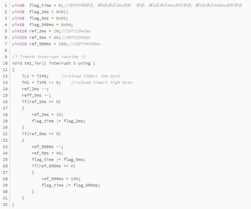
(1) The ref_2ms register continuously decrements by 1 every interrupt, a total of 16 times, so the elapsed time is 125us × 16 = 2ms, which is what we call a timer/counter. This allows us to use a single system RTC interrupt to achieve many required timing intervals.(2) Set the 2ms timing end flag, which is used by the time-handling program. This is the framework for a timer, and the 5ms timer operates in exactly the same way. The above program is the timer within the interrupt service routine, timing at 2ms, 5ms, and 500ms, with overflow indicated by the flag_time flag, allowing the program to know whether the timing has been reached.(2) Now let’s look at the unified time service subroutine
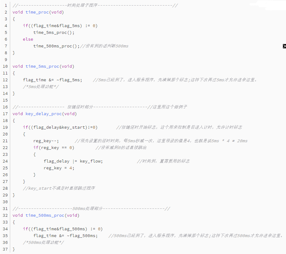
The above uses a 20ms debounce timer as an example. Once understood, you can find that we can completely mimic that timer and place many more timers below. Each timer counts simultaneously every 5ms, and whichever finishes first will turn itself off and set the appropriate flag for other programs to call, without affecting the other timers! Thus, we can place many timers here; generally, having a dozen or so is not a problem, fully meeting a microcontroller system’s demand for multiple timing intervals. The structure of a single timer is quite simple: first, check if the timing flag is allowed to enter timing, then a dedicated register increments or decrements by 1. After adding or subtracting the corresponding value, when the respective time is reached, the timer turns off and sets the necessary flags. That’s about it; we can get all the timing we need. Isn’t this very convenient? Now let’s see what the microcontroller has been doing during this time. Only when the interrupt timing reaches 5ms or 500ms will the overflow flag become valid, allowing entry into the above timing program; at other times, it is performing other tasks. Moreover, when entering the above timer, it is clear that it is not stuck in a dead loop; it simply increments or decrements a register and exits, taking an extremely short time—about 5us to 20us—thus having no impact on the execution of the main program.(3) Now let’s see how to call this The previously discussed key debounce timing issue will now be addressed using the method introduced above. Key handling is also an important foundational knowledge, but it is not within the scope of this discussion, so we will only focus on how to solve the timing problem; we can discuss key issues next time if there’s an opportunity, hoho~~~
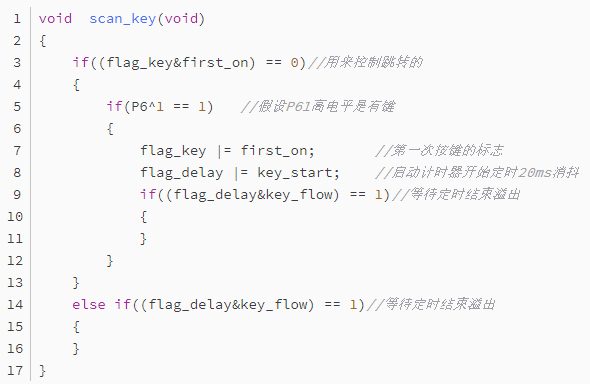
That’s about it: Determine when a key is pressed; if not, exit. If pressed, start the debounce timing. The second time entering, directly control based on the flag whether the time is sufficient. Similarly, this is the last point mentioned; we are running while waiting, not standing still while waiting. Compared to a dead loop, during the time when the debounce has not reached 20ms, what is the microcontroller doing? In a dead loop, it would be waiting in place, doing nothing. However, looking at the above program, it merely checks if the timing is sufficient; the actual timing is done in the unified time subroutine. If the time has not yet reached, it exits and continues to run other programs until the time has arrived, and the microcontroller determines that flag_delay and key_flow meet the conditions, beginning to enter the key handling program. During this period, the microcontroller can run other programs completely, as it only checks once in the main loop.(4) Let’s take a look at my main program loop
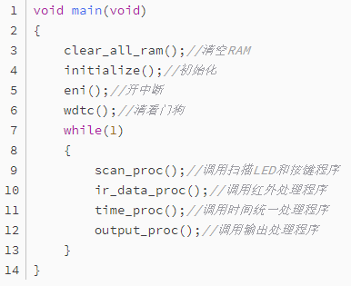
This is my loop body; all functions are written as subroutines, making it convenient to attach as needed. This way, the microcontroller is continuously executing this loop body. If the entire program adopts the aforementioned time-slice scanning idea, the time to loop back is quite short. Isn’t it somewhat similar to the concept of computers? A computer, no matter how fast, does not process multiple tasks simultaneously; it processes one at a time very quickly, giving us the impression that it is handling multiple programs at once. I want to express that the idea I am conveying is just that.
After rambling on, I don’t know if it’s understandable or if anyone will read it. I wonder if my understanding of the time-slice scanning concept is correct? In my view, with this idea supporting it, programming for microcontrollers becomes relatively easy; the remaining task is merely to concentrate on using the program to realize our ideas. Of course, this is just one feasible method, not the only one. If anyone has better ideas, please share them. Writing programs is an art; it is easy to write them, but writing them well and elegantly is quite challenging.


1. The guests for the Domestic Embedded Operating System Technology and Industry Development Forum and the Embedded System Association Thematic Discussion Meeting are announced!
2. Programming Language Trend Forecast: Rust will become mainstream, React continues to dominate the programming world.
3. Teach you how to quickly create sliding applications using TouchGFX.
4. Has today’s FPGA taken a wrong turn?
5. How many American chips does Huawei’s mobile phone actually use?
6. Have you seen an Arduino that is 10.3mm x 11.5mm?

Disclaimer: This article is a network reprint, and the copyright belongs to the original author. If there are any copyright issues, please contact us. We will confirm copyright based on the copyright proof materials you provide and pay remuneration or delete content.