Click the blue text to follow us


Today, we will introduce the magnetic linear displacement sensor compatible with the American DELTA motion controller.


Industry News Overview

Magnetic Linear Displacement Sensor

Magnetic linear displacement sensors are divided into built-in and external types.
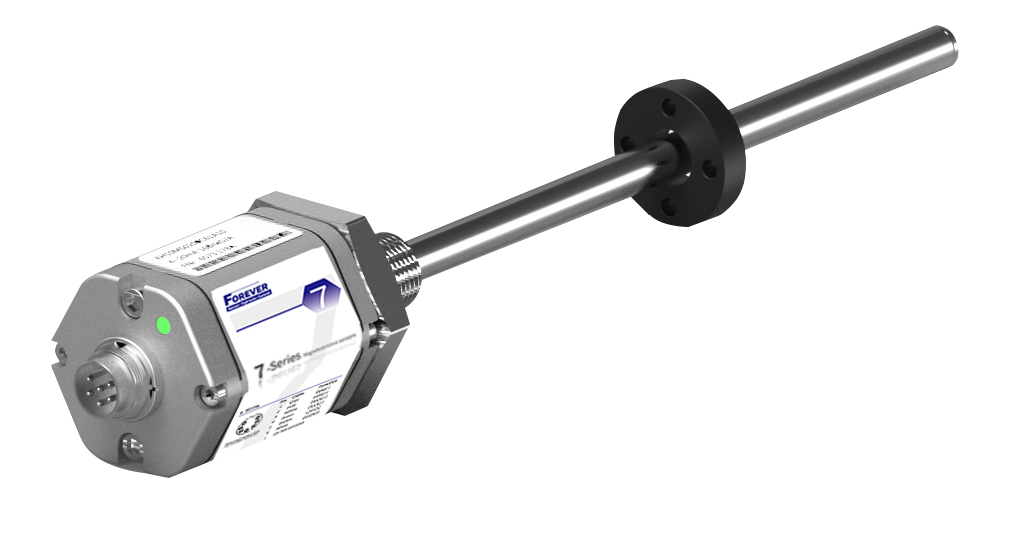
Built-in installation
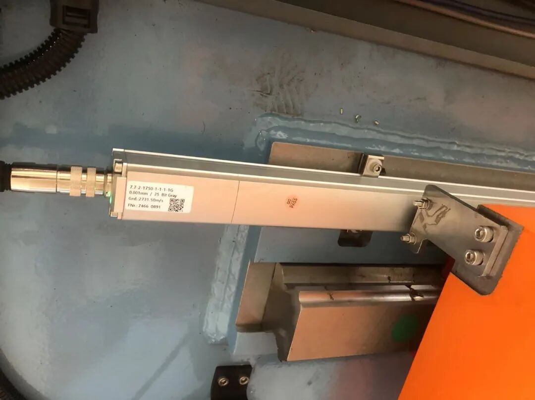
External installation
Introduction to the Principle of Magnetic Linear Sensors

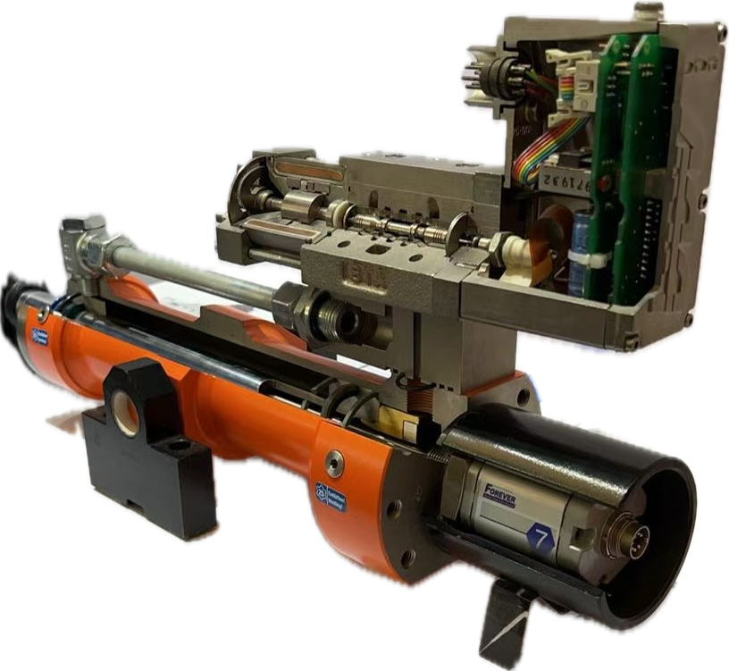
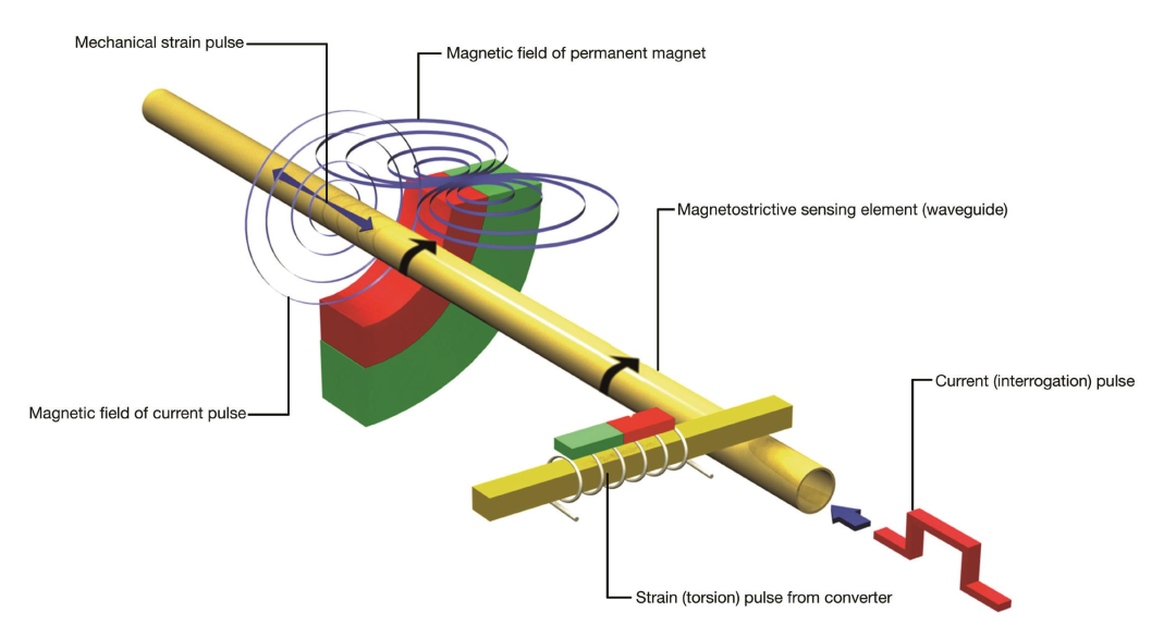
The magnetic linear displacement sensor mainly consists of a non-magnetic stainless steel pressure-resistant outer tube, waveguide wire, movable magnetic ring, and measurement processing circuit.The waveguide wire is installed inside the stainless steel tube to maintain electromagnetic properties, and the magnetic ring can slide freely outside the stainless steel tube, while the measurement processing circuit is integrated in the electronic chamber at the sensor head.
The measurement processing circuit generates periodic electrical pulses, which create a radial magnetic field on the waveguide wire. When the radial magnetic field generated by the pulse current collides with the axial magnetic field produced by the cursor magnet, a helical magnetic field is synthesized. Based on the “Weidmann Effect” of magnetic materials, the waveguide wire undergoes local instantaneous deformation and generates torsional waves. After the torsional waves are generated, they propagate in opposite directions at a certain speed. The torsional wave directed towards the tail end of the sensor is a useless wave, which will ultimately be absorbed by the damping at the tail end of the sensor, while the torsional wave directed towards the electronic chamber is an effective wave, generating an electrical pulse at the receiving coil. Based on this electrical pulse and the time difference from the initial inquiry pulse generated by the sensor, as well as the speed of the torsional wave in the waveguide wire (generally 2780m/s), we can calculate the displacement between the magnet and the coil, and the accuracy of the displacement is related to the timing accuracy.
Introduction to SSI Protocol

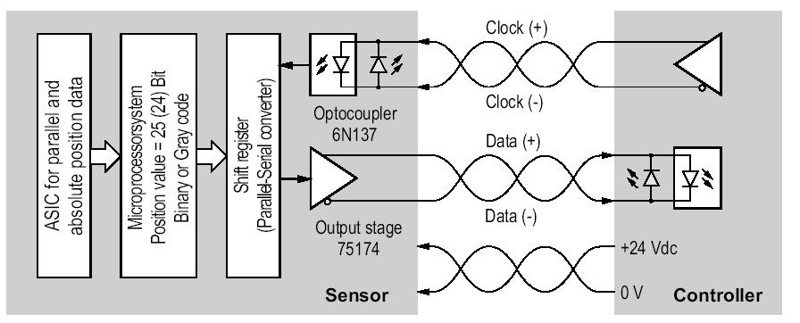
SSI communication protocol is an abbreviation for Synchronous Serial Interface, which is a widely used signal for displacement sensors/encoders.
SSI is a unidirectional serial protocol based on RS-422. The unidirectional clock is generated by the master frequency, ranging from 80kHz to 2MHz. The received data is also unidirectional.
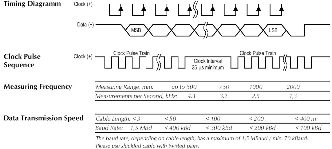
When inactive, the clock is at a high level. To initiate data transmission, the clock level is pulled low and the position is stored. On the first rising edge of the clock signal, the MSB data bit is output from the SSI encoder. On the second rising edge, the MSB-1 data bit is output, and so on, until the last bit (LSB data bit) is output. The clock remains high until the next data transmission cycle begins.
SSI signals from displacement sensors are typically the optimal choice for servo hydraulic motion control, and currently, the highest resolution of SSI sensors on the market can reach 0.1um.
Introduction to Start/Stop Signals

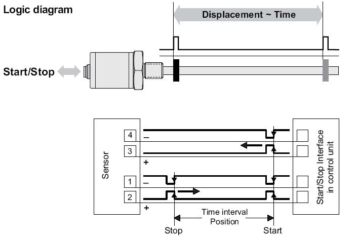
The Start/Stop signal is a unique signal for displacement sensors based on the Time of Flight (TOF) principle, commonly found in magnetic linear sensors and laser distance sensors.
The Start and Stop signals represent the beginning and end of the time period, respectively. The Start signal is usually generated by the controller at a fixed inquiry cycle, during which the magnetic linear sensor generates an inquiry pulse level signal internally. Upon receiving the pulse signal output from the coil, the circuit converts it into a standard level Stop signal, which is returned to the controller. The controller calculates the time difference between the Start and Stop signals, multiplies it by the waveguide transmission rate specified on the sensor nameplate, and can then convert it to the actual position of the magnet.
Advantages of Magnetic Linear Sensors:
• Non-contact measurement
• High accuracy
• Large measurement range
• High protection level
• Absolute output
• Simple and convenient installation, debugging, and maintenance
• Multiple signal types
• Multi-position measurement

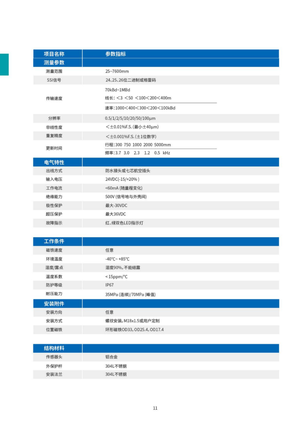
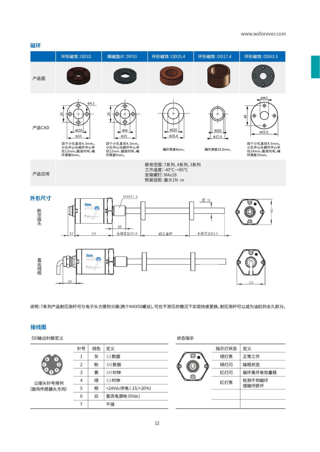
Attached is the FOREVER built-in series 7.1 magnetic linear displacement sensor SSI sample for your reference:
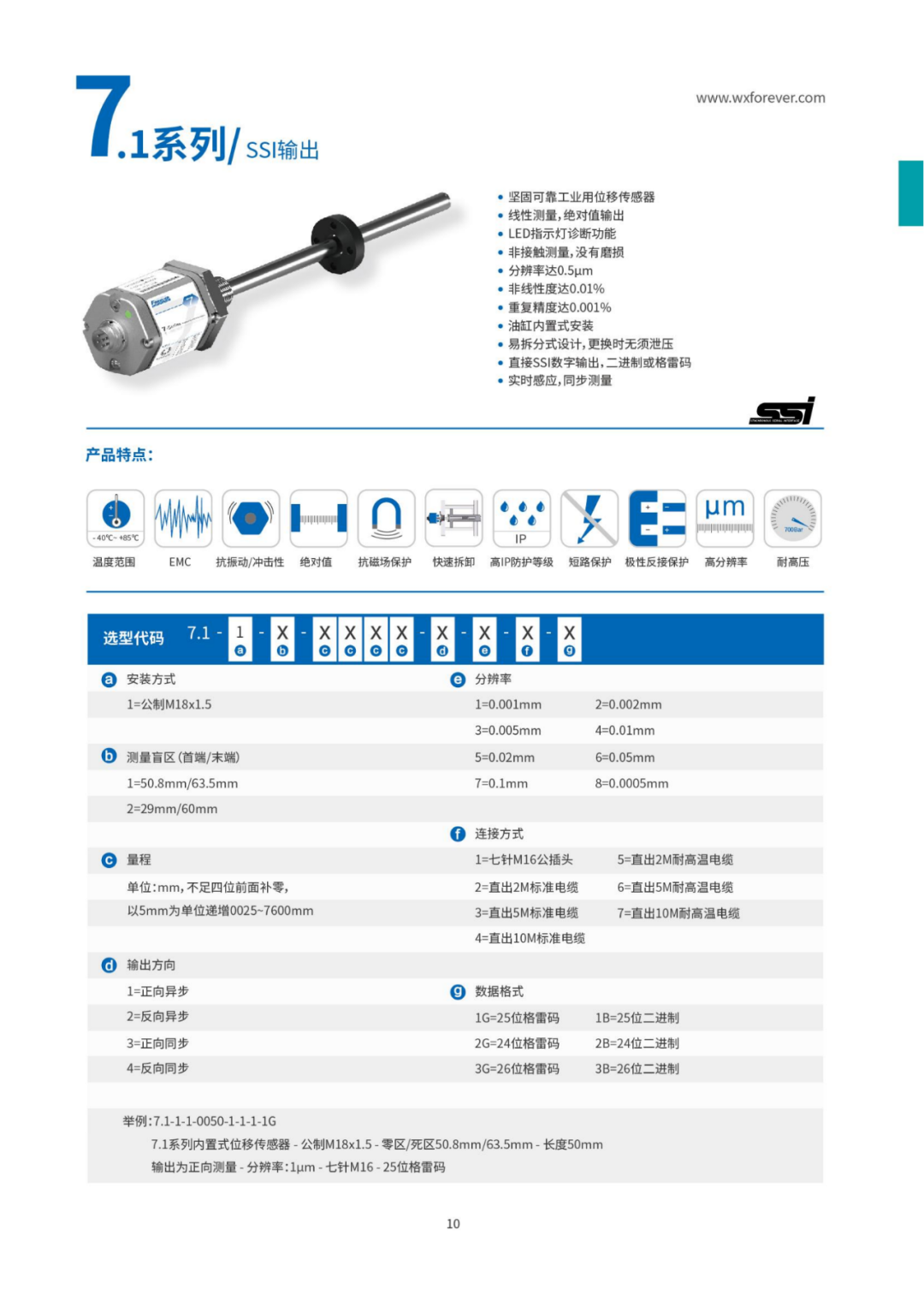
If you need more sensor selection samples, please contact us directly.


Conclusion
 Please follow the next issue:Basic training on the American DELTA motion controller (Part 5) Introduction to resistive sensors, LVDT, magnetic grating, and optical grating.