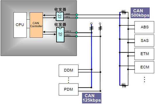
Examples of CAN Applications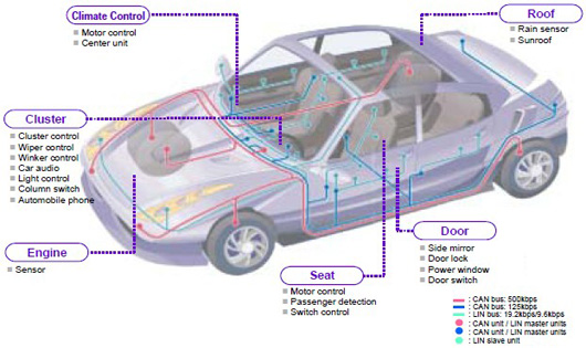 Bus Topology DiagramThe CAN controller determines the bus level based on the potential difference on the two wires. The bus level is divided into dominant and recessive levels, one of which must be present. The sender sends a message to the receiver by changing the bus level.CAN Connection Diagram
 Features of CANCAN protocol has the following features:(1) Multi-Master Control When the bus is idle, all units can start sending messages (multi-master control).The unit that first accesses the bus gains the right to send (CSMA/CA method).If multiple units start sending simultaneously, the unit sending the higher priority ID message gains the right to send.(2) Message SendingIn the CAN protocol, all messages are sent in a fixed format.When the bus is idle, all units connected to the bus can start sending new messages.When two or more units start sending messages simultaneously, priority is determined based on the identifier (Identifier hereafter referred to as ID). The ID does not indicate the destination address but represents the priority of the message accessing the bus. When two or more units start sending messages simultaneously, each bit of the message ID is compared one by one for arbitration. The unit that wins arbitration (determined to have the highest priority) can continue sending the message, while the unit that loses arbitration will immediately stop sending and switch to receiving mode.(3) System Flexibility Units connected to the bus do not have information similar to an “address”. Therefore, when adding units to the bus, the hardware and application layer of other units connected to the bus do not need to change.(4) Communication Speed The appropriate communication speed can be set based on the scale of the entire network.In the same network, all units must be set to a unified communication speed. Even if one unit’s communication speed is different from the others, that unit will output an error signal, disrupting communication across the entire network. Different networks can have different communication speeds.(5) Remote Data Request Data can be requested from other units by sending a “remote frame”.(6) Error Detection Function·Error Notification Function·Error Recovery FunctionAll units can detect errors (error detection function). The unit that detects an error will immediately notify all other units (error notification function). If a unit currently sending a message detects an error, it will forcibly terminate the current transmission. The unit that forcefully ends the transmission will repeatedly attempt to resend the message until successful (error recovery function).(7) Fault IsolationCAN can determine whether the type of error is a temporary data error on the bus (such as external noise) or a persistent data error (such as internal unit failure, driver failure, disconnection, etc.). With this function, when a persistent data error occurs on the bus, the unit causing the fault can be isolated from the bus.(8) Connections CAN bus can connect multiple units simultaneously. The theoretical number of connectable units is unlimited. However, in practice, the number of connectable units is limited by the time delay and electrical load on the bus. Reducing communication speed increases the number of connectable units; increasing communication speed decreases the number of connectable units.Types of CAN Error States Units are always in one of three states.(1) Active Error State The active error state is the state that can participate normally in bus communication. Units in the active error state output an active error flag when they detect an error.(2) Passive Error State The passive error state is a state prone to errors. Units in the passive error state can participate in bus communication but cannot actively send error notifications to avoid disrupting communication with other units. Units in the passive error state output a passive error flag when they detect an error, even if other units in the active error state do not detect any errors, the entire bus is considered error-free. Additionally, units in the passive error state cannot immediately start sending again after sending ends. They must insert a “delay transmission” (8 bit recessive bits) during the interval frame before starting the next transmission.(3) Bus Off State The bus off state is a state that cannot participate in bus communication. Both receiving and sending information are prohibited. These states are managed by sending error counts and receiving error counts, with the count value determining which state to enter. The relationship between error states and count values is shown in Table1 and the diagram.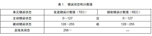
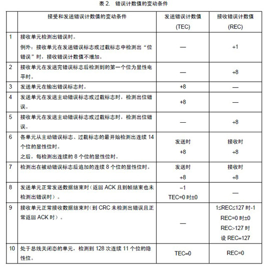
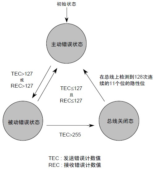 Figure: Error States of UnitsError Count ValuesSend error count values and receive error count values change based on certain conditions. The conditions for error count value changes are shown in Table 2 . Receiving and sending data may simultaneously meet multiple conditions.The error counter starts counting at the time the first bit of the error flag appears.
 Basic Reference Model of CAN Protocol The CAN protocol covers the transport layer, data link layer, and physical layer defined by ISO, as shown in Table3.The definitions regarding the transport layer, data link layer, and physical layer in the CAN protocol are illustrated in the figure.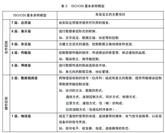
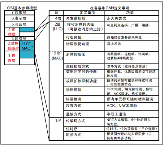 Figure:ISO/OSI Basic Reference Model andCAN Protocol The data link layer is divided into MAC sublayer and LLC sublayer, the MAC sub-layer is the core part of the CAN protocol. The function of the data link layer is to organize signals received from the physical layer into meaningful messages and provide processes for transmission control such as error control. Specifically, this includes framing, arbitration, acknowledgment, error detection or reporting. The functions of the data link layer are typically performed in the hardware of the CAN controller. In the physical layer, the actual method of sending signals, bit timing, bit encoding method, and synchronization steps are defined. However, signal levels, communication speeds, sampling points, electrical characteristics of drivers and buses, and connector forms are not defined. These must be determined by the user according to system requirements.ISO Standardized CAN ProtocolThe CAN protocol has been standardized by ISO into two standards: ISO11898 and ISO11519-2. ISO11898 andISO11519-2 standards have the same definitions for the data link layer, but different physical layers. (1) AboutISO11898 ISO11898 is the CAN high-speed communication standard with a communication speed of125kbps-1Mbps . Currently,ISO11898 has become the new standard ISO11898-1 after adding new regulations. (2) AboutISO11519ISO11519 is the CAN low-speed communication standard with a communication speed below 125kbps . ISO11519-2 is the version after adding new regulations to ISO11519-1. The following figure represents the scope of the CAN protocol and ISO11898 andISO11519-2 standards.
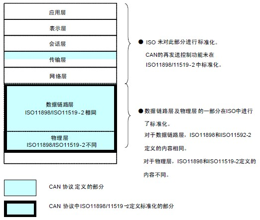 Figure:ISO StandardizedCAN ProtocolCAN and Standard SpecificationsNot only ISO, but also other organizations, groups, and companies such as SAE have standardized the CAN protocol.Various standard specifications based onCAN are shown in Table6 and illustrated in the figure, categorizing automotive communication protocols based on communication speed.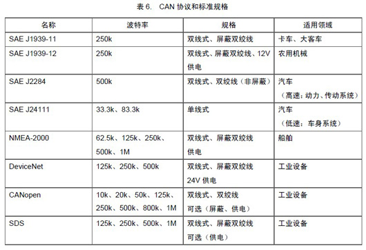
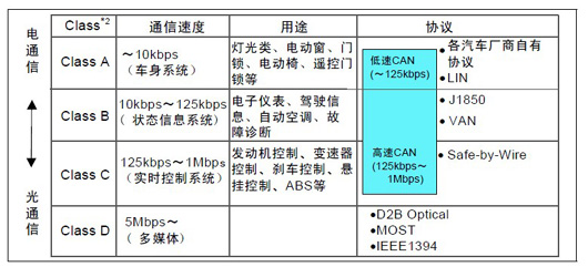 Figure: Communication Protocol Classification
(Images sourced from the internet)
Source: Automotive Maintenance and Repair
 ● Warning! Don’t attempt to repair new energy vehicles if you don’t understand; be careful with your life! ● CCTV exposes investment scams in charging piles; is this “pile” business really easy to do? ● How to charge a small battery of new energy vehicles when it runs out of power● CCTV exposes investment scams in charging piles; is this “pile” business really easy to do?