
Integrated constant current mode and high voltage start current modePWM controller switch power supply chipU7575 is a high-performance current modePWM controller designed for offline flyback converters. The chip integrates a universal primary side constant current control technology, supporting both discontinuous mode and continuous mode operation, without the need for an additional constant current loop, making it suitable for isolated power applications requiring constant current, such as chargers, adapters, and motor drive power supplies.
Main features of the switch power supply chip U7575:
▲ Integrated high voltage start function
▲ Supports primary side constant current technology in discontinuous mode and continuous mode
▲ ±5% constant current accuracy; ±1% constant voltage accuracy
▲ Standby power consumption <50mW
▲ Built-in slope compensation current mode control fixed
▲ 65kHz switching frequency jitter function optimizes EMI
▲ Green energy-saving mode and hiccup mode operation
▲ Ultra-low start and operating current
▲ Integrated self-recovery mode protection functions:
VDD undervoltage protection (VDD UVLO)
VDD overvoltage protection (VDD OVP)
Output overvoltage protection (CS OVP)
Short circuit protection (SCP)
Cycle-by-cycle current limiting
Overload protection (OLP)
Leading edge blanking (LEB)
▲ Package type SOP-8

Switch power supply chipU7575 pin names:
1 SEL function multiplex pin. For constant current constant voltage output applications, it is recommended to connect a typical value capacitor of 10-47nF to the GND pin; for constant voltage output applications, this pin should be left floating.
2 FB feedback input pin. Connect to the optocoupler in closed-loop control; the voltage on this pin determines the duty cycle of the PWM driving signal and the shut-off voltage of the CS pin.
3 CS current sampling input and OVP multiplex pin.
4 GND chip reference ground.
5 GATE totem pole driver circuit pin, connected to external MOSFET.
6 VDD chip power supply pin.
7 NC non-functional pin left floating during use.
8 HV high voltage start pin.
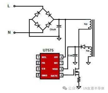
The switch power supply chip U7575 integrates a high voltage start module. The diagram below shows one high voltage start circuit configuration for U7575. The chip’s HV pin is connected to the BUS capacitor after the rectifier bridge. During startup, the internal high voltage start module is enabled, and the internal high voltage current source charges the VDD capacitor. When VDD is less than 2V, the HV supply current is 0.5mA, and when VDD is greater than 2V, the HV supply current increases to 5mA. When the VDD voltage increases to the chip’s turn-on voltage of 12V (typical value), the chip begins to operate, and the chip’s operating current increases to 2mA (typical value). After that, the VDD capacitor continues to supply power to the chip until the output voltage is established and powered by the auxiliary winding Na.
