ON Semiconductor released the LLC current mode controller NCP1399 in the third quarter of 2016, addressing the shortcomings of the LLC controller’s purely voltage-frequency mode. In official comparisons, it performs excellently compared to NXP’s TEA1716 (which I have used in ARM projects).
● Power Characteristics① Universal AC input range. ② Active PFC, PF>0.97. ③ Efficiency over 92%. ④ Protection types: overcurrent, overvoltage, overtemperature, short-circuit. ⑤ Waterproof encapsulation. ⑥ Natural air cooling.● Design Chips and Solutions① PFC control chip ICE3PCS03G
② LLC chip NCP1399● Design Related DocumentsLLC transformer design reference from Guo Chunming’s design document

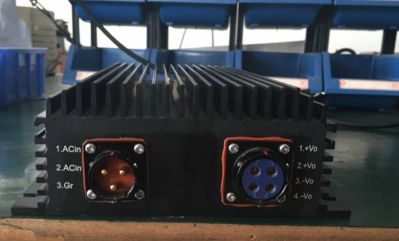
01
Product Image
02
Introduction to the Control Frequency of This Chip
First, take a picture to upload.
❶ Traditional LLC control chips such as 6599 and NXP’s TEA1716 operate in voltage mode frequency control. That is, the frequency is high under no load and decreases under heavy load.
❷ In contrast, NCP1399 operates in current mode, maintaining a stable frequency of 70K from light to heavy load, with pulse width varying, indicating it is likely a pulse-width modulation controller.
❸ Given the different control methods, voltage mode has a relatively slow response. Without secondary overcurrent protection, issues can arise in primary control, leading to hard switching and even damage to the MOSFETs. The NCP1399 current mode allows for soft switching while protecting the MOSFETs in primary control.
03
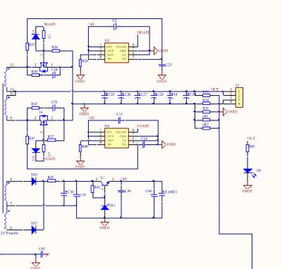
PFC Section
Discussing the PFC section, the chip uses Infineon’s CCM control chip. Below are its characteristics: ICE3PCS03G is a new 8-pin wide input range (85VAC to 265VAC) controller IC for active CCM power factor correction converters. Compared to the first and second generations ICE1PCS0x and ICE2PCS0x, the third generation PFC features a lower 2.5V internal reference adjustment and integrated digital control voltage loop. Additionally, it has advantages like low peak current limit at 0.2V, adjustable gate switching frequency range from 21kHz to 250kHz, and the capability to synchronize with external frequency ranges from 50kHz to 150kHz. It can now achieve 95% efficiency at full load across all input voltage ranges. The external circuit is relatively simple, providing under-voltage, open-loop, and over-voltage protection. The integrated digital control easily achieves a PF value above 0.98. It is recommended to use this chip for PFC under 1000W, which is quite good.
PFC section schematic
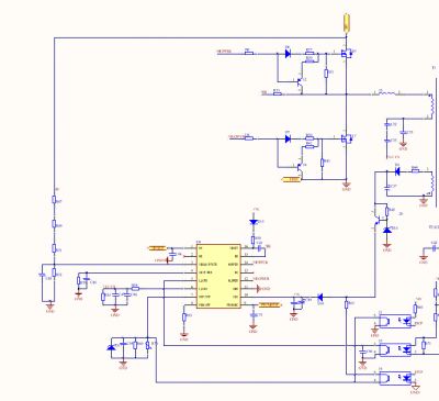
NCP1399 has a complete power startup sequence, gap mode, and other power supply control systems. However, due to the lack of auxiliary power, you cannot externally connect the driver (which requires greater power supply capability), thus limiting its maximum power capability. The official recommendation for NCP1399 is up to 600W (I remember ON’s engineers recommended 600W).
NCP1399’s pin 3, VBULK/PFCFB, can be shared with the PFC’s FB pin according to the official example, but during one debugging session, connecting VBULK/PFCFB to ground caused the PFC’s FB pin to adjust the voltage to 500V, so I suggest keeping it separate in some cases for setting.
Pin 1 of NCP1399 has a high-voltage startup cross-charging feature, which is also a feature of ON’s products. The voltage on this pin should be connected from a separate rectified resistance voltage divider before the rectifier bridge (refer to the official example), and it is best to add a high-voltage ceramic capacitor for filtering before entering the HV pin.
The voltage of NCP1399 is not a stable value at light load; it will fluctuate between the set voltage values and can be eliminated after loading. Of course, you can add a small dummy load or appropriately adjust the resistance value of pin 4 skip for suitable settings.
To achieve energy-saving, pin 8 has the function of turning off PFC under light load. You can set it to a resistance value of 1K; if you do not want to consider this issue, you can connect a 0R resistor to ground.
The remaining power supply pins, drive pins, and other LLC chips are similar. When using the chip’s built-in driver, choose suitable resistors to avoid overloading the chip.
NCP1399’s drive capability is 0.5A/1A.
04
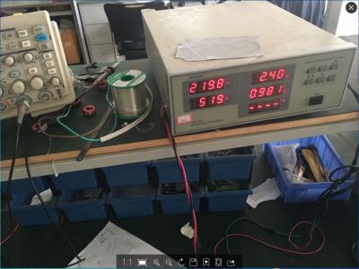
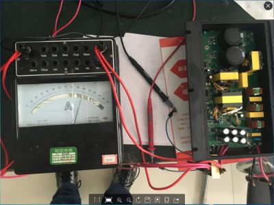
Efficiency Test Images at 500W
Power Meter

Output Current
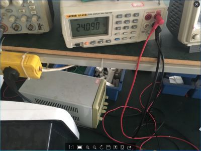
Output Voltage
Output current 10.1*2=20.2A, voltage 24.09V, input power 519W (20.2*24.09)/519=0.937,600W testing achieved 93% efficiency.
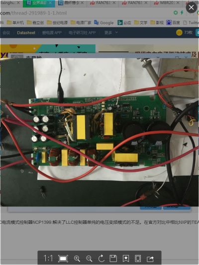
05
Principle and PCB
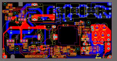
PCB
Secondary
Primary
◆ trzhangwei
Hello, may I ask which MOS you selected for PFC? Which diode did you choose for PFC? Also, is it unnecessary to add a totem for PFC drive? I want to use 6599 for LLC (which I am familiar with), the driving current and injection current are 0.3/0.8A, so should I add a totem for the drive? Can you provide some guidance?
◆ Lixinghua
PFC MOS selected ST’s STW45NM60, PFC diode I chose Infineon’s IDH16G65C5, this selection is too large, an 8A one would be enough (I only had this SIC diode at hand).
While the driving capability of 6599 is small, it should be fine under 300W, and beyond that, I think it should still be okay, at worst, it will switch on slower, slightly affecting efficiency, but the discharge of the MOS must include a transistor to increase the discharge speed.
◆ jie28021
I’d like to know if you added the transistor at the LLC?
◆ lixinghua
For LLC under 600W, I did not add a driver, but for 1000W, I did add a driver. I am currently debugging the 1000W LLC.

Due to space limitations, this article only selects parts of the content. Click on “Read Original” at the end to jump to the 21Dianyuan community to see more content and participate in discussions!

↓↓↓ Click “Read Original” for more content!